Cutter abrasion loss monitoring method based on simulation feature and signal feature fusion

A technology of tool wear and signal characteristics, used in manufacturing tools, measuring/indicating equipment, metal processing machinery parts, etc., can solve problems such as reduced factory operating efficiency and reduced automation, and achieve accurate simulation results, improve accuracy, reduce The effect of workload

Pending Publication Date: 2022-03-11
FUZHOU UNIV
View PDF0 Cites 0 Cited by
  • Summary
  • Abstract
  • Description
  • Claims
  • Application Information

AI Technical Summary

Problems solved by technology

In modern processing plants, processing tends to be integrated and automated, and downtime means reduced automation and reduced operating efficiency of the factory, which is very undesirable for modern processing

Method used


Image

  • Cutter abrasion loss monitoring method based on simulation feature and signal feature fusion
  • Cutter abrasion loss monitoring method based on simulation feature and signal feature fusion
  • Cutter abrasion loss monitoring method based on simulation feature and signal feature fusion

Examples


Embodiment Construction

[0040] The invention will be further described below with reference to the accompanying drawings and examples.

[0041] It should be noted that the following detailed description is illustrative and is intended to provide a further description of the present application. All techniques and scientific terms used herein have the same meaning as commonly understood by those of ordinary skill in the art of the present application.

[0042] It should be noted that the terms used herein are intended to describe specific embodiments, and not intended to limit the exemplary embodiments of the present application. As used herein, unless the context further explicitly indicates that the singular form is intended to include multiple forms, but it should be understood that when the term "including" and / or "includes" in this specification, it indicates There is a combination of features, steps, operations, devices, components, and / or their combinations.

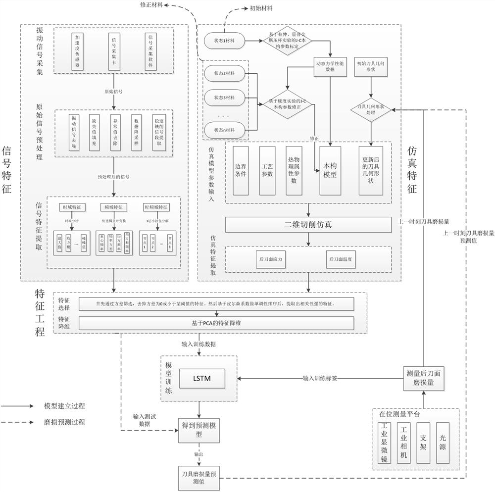
[0043] Such as figure 1 As shown, ...


PUM


Abstract

The invention relates to a tool wear loss monitoring method based on simulation feature and signal feature fusion, which comprises the following steps: S1, acquiring an original vibration signal, and measuring the wear loss of a rear tool surface; s2, performing signal preprocessing on the original vibration signal and extracting signal features; s3, performing J-C constitutive model parameter calibration of the first-state material based on stretching, compression and Hopkinson pressure bar experiments; s4, performing J-C constitutive model correction of other state materials except the first state material based on the hardness experiment; s5, acquiring simulation characteristics of the same material in different states; s6, performing feature selection and feature dimension reduction on the signal features and the simulation features to obtain fused low-dimension features; s7, training an LSTM (Long Short Term Memory) model according to the dimensionality-reduced features obtained by feeding each time and the corresponding flank abrasion loss; and S8, the abrasion loss of the rear tool face is obtained after the features obtained through each feeding are input. According to the method, the workload of model correction is reduced, repeated experiments are avoided, and meanwhile the precision of the model can be improved.

Description

Technical field [0001] The present invention relates to a tool wear monitoring technology, and more particularly a method for monitoring tool wear characteristics and signal characteristics simulation fusion. Background technique [0002] The tool will inevitably wear during processing, tool wear can affect the process, resulting in a decline of the quality of surface processing, even when serious accidents occur machining. When the tool reaches the standard blunt, timely replacement of the tool should avoid the use of the tool after the machining of the workpiece abrasion process has decreased surface quality. However, in the process operators often do not know the specific tool wear, can only be judged by the experience of tool wear or use the machine to stop. Currently, the detection processing tool downtime wear of the total process of 20%, 3% to 12% of the production costs and costs related to the tool. In modern processing plants, the process tends to integration, automatio...

Claims


Application Information

Patent Timeline
Patent Type & Authority Applications(China)
IPC IPC(8): B23Q17/09
CPCB23Q17/0957
Inventor 俞建超鲁治锴丁宇星
Owner FUZHOU UNIV
Why Eureka
Try Eureka