
Fluorescent optical fiber temperature measuring system for biomedicine

A fluorescent optical fiber and temperature measurement technology, which is applied in the field of fluorescent optical fiber temperature measurement system, can solve the problems of the measurement accuracy and response speed of the fluorescent thermometer, prolong the signal processing time, and complicate program design, etc., and achieve simple detection circuit scheme and low cost. Low, the effect of improving the measurement accuracy

Pending Publication Date: 2022-03-11
HEBEI NORMAL UNIV
View PDF0 Cites 1 Cited by
  • Summary
  • Abstract
  • Description
  • Claims
  • Application Information

AI Technical Summary

Problems solved by technology

At present, there are quite a number of data processing schemes for detecting fluorescence lifetime, but these schemes have obvious deficiencies, such as failing to utilize the information contained in the entire decay process, measuring the dynamic range and cumbersome numerical algorithms, which make the program design complicated and extremely difficult. Large extended signal processing time, etc.
The obvious defects of these schemes have seriously affected the measurement accuracy and response speed of the fluorescence thermometer, making it difficult to popularize.

Method used


Image

  • Fluorescent optical fiber temperature measuring system for biomedicine
  • Fluorescent optical fiber temperature measuring system for biomedicine
  • Fluorescent optical fiber temperature measuring system for biomedicine

Examples


Embodiment Construction

[0028] The following will clearly and completely describe the technical solutions in the embodiments of the present invention with reference to the accompanying drawings in the embodiments of the present invention. Obviously, the described embodiments are only some, not all, embodiments of the present invention. Based on the embodiments of the present invention, all other embodiments obtained by persons of ordinary skill in the art without making creative efforts belong to the protection scope of the present invention.

[0029] In the present invention, unless otherwise clearly specified and limited, terms such as "installation", "connection", "connection" and "fixation" should be understood in a broad sense, for example, it can be a fixed connection or a detachable connection , or integrated; it can be mechanically connected or electrically connected; it can be directly connected or indirectly connected through an intermediary, and it can be the internal communication of two c...


PUM


Abstract

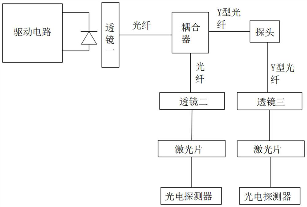
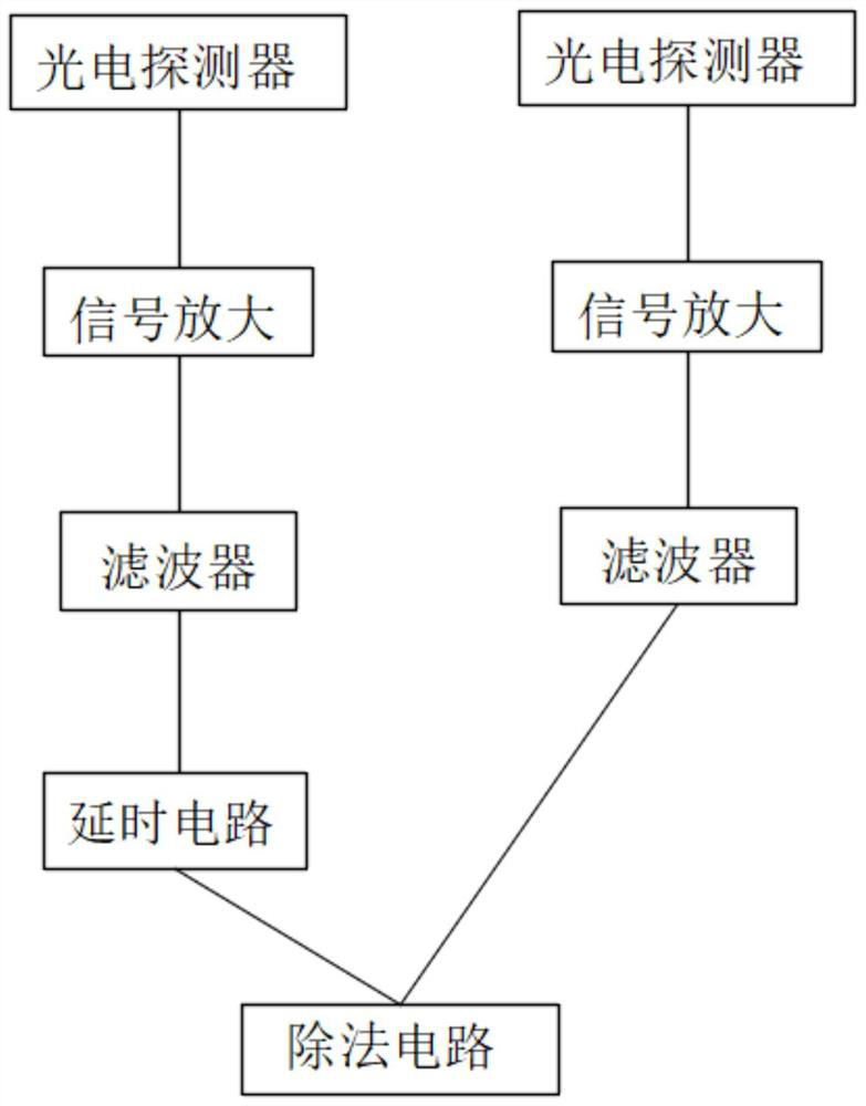
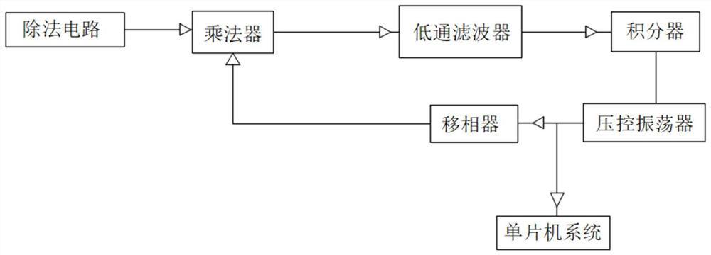
The invention relates to the technical field of optical fiber temperature measurement, in particular to a fluorescent optical fiber temperature measurement system for biomedicine, which comprises a probe, a coupler and a driving circuit, the output end of the coupler is connected with a lens I through an optical fiber, the coupler is connected with the probe through a Y-shaped optical fiber, and the probe is connected with a lens III through a Y-shaped optical fiber. The sides, away from the optical fiber, of the second lens and the third lens are each provided with a laser sheet, the sides, away from the optical fiber, of the laser sheets are connected with a photoelectric detector, the output end of the photoelectric detector is connected with a signal amplification circuit, and the output end of the amplification circuit is connected with a filter. The filter output end connected with one end of the Y-shaped optical fiber is connected with a division circuit. According to the fluorescence optical fiber temperature measurement system for biomedicine, the reference signal related to the reference excitation signal is adopted, the influence of inherent excitation light leakage of a phase locking scheme on a fluorescence fading signal is successfully solved, and the measurement precision is remarkably improved.

Description

technical field [0001] The invention relates to the technical field of optical fiber temperature measurement, in particular to a fluorescent optical fiber temperature measurement system for biomedicine. Background technique [0002] The test of fluorescence lifetime only involves the relative intensity of fluorescence at the test point during the process of fluorescence decay, and the test of fluorescence lifetime is only related to the properties of the fluorescent temperature sensing probe and the working temperature, and has nothing to do with the intensity of pump light and the optical path transfer factor. The test results It will not be affected by changes in the coupling conditions of the entire fiber and the state of the optical path. [0003] Fluorescence temperature measurement is a new type of temperature measurement technology developed in recent years. There are many measurement schemes for fluorescence lifetime in foreign literature, among which the application...

Claims


Application Information

Patent Timeline
Patent Type & Authority Applications(China)
IPC IPC(8): G01K11/32
CPCG01K11/32
Inventor 武金玲杜皓王丹
Owner HEBEI NORMAL UNIV
Learn More