Supercharge Your Innovation With Domain-Expert AI Agents!

Collaborative robot joint and collaborative robot

A technology of robot joints and encoders, applied in manipulators, program-controlled manipulators, manufacturing tools, etc., can solve the single-turn absolute encoder structure, the difficulty of lightweight design, the self-heavyness of collaborative robot joints, cost and production impact, etc. problems, to achieve the effect of excellent waterproof and dustproof performance, compact structure, and improved yield rate

Pending Publication Date: 2022-03-15
成都卡诺普机器人技术股份有限公司
View PDF0 Cites 1 Cited by
  • Summary
  • Abstract
  • Description
  • Claims
  • Application Information

AI Technical Summary

Problems solved by technology

[0004] 1) The joint weight of collaborative robots is relatively large, and the design must follow the lightweight safety design principles. Therefore, very high requirements are put forward for the integration of collaborative robots. At present, the integration of collaborative robots needs to be improved
[0005] 2) The use of two single-turn absolute encoders has certain difficulties in terms of structure and lightweight design, especially the assembly and layout of related cables, which have a great impact on cost and production
[0006] 3) The brake structure of the friction plate is adopted. When the robot presses the human hand or equipment, the robot cannot move in a small range when the power is off. For the collaborative robot, there are obvious loopholes in its safety

Method used


Image

  • Collaborative robot joint and collaborative robot
  • Collaborative robot joint and collaborative robot
  • Collaborative robot joint and collaborative robot

Examples


Embodiment 1

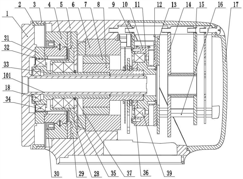
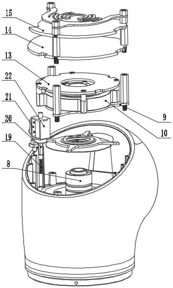
[0038] see Figure 1-2 , a collaborative robot joint, comprising a harmonic reducer front cover 1, an accommodation space formed by a housing 5 and a rear cover 17, and a harmonic reducer assembly located in the accommodation space, a crossed roller bearing 4, and a motor assembly , brake components, encoder components, drive components.

[0039] see figure 1 The motor assembly includes a frameless torque motor and a rotor shaft 8 installed coaxially. The frameless torque motor includes a stator 6 and a rotor 7 . The rotor 7 is fixedly mounted on the rotor shaft 8 , and the stator 6 is fixedly mounted on the housing 5 .

[0040] see figure 1, the harmonic reducer assembly includes a harmonic reducer rear end cover 29 installed coaxially, a harmonic reducer input shaft 33, a double-covered deep groove ball bearing assembly 28, a harmonic reducer and the first deep groove ball bearing 18. One end of the input shaft 33 of the harmonic reducer is fixedly installed on the rotor...

Embodiment approach

[0046] For an implementation, see Figure 7 , the encoder rotor flange 11 is provided with a first positioning step 111 , and the encoder rotor 12 is installed on the first positioning step 111 of the encoder rotor flange 11 . Specifically, a plurality of screws parallel to the axis fixes the encoder rotor 12 on the first positioning step 111 of the encoder rotor flange 11, that is, the screws are installed axially, and of course, non-axial installation; and can also be installed in combination with reference to the above-mentioned interference fit.

[0047] see Figure 8 , Figure 8 Another structure of the encoder assembly is shown, the encoder rotor 12 is connected with a mounting positioning ring 43 , and the mounting positioning ring 43 is connected with the encoder rotor flange 11 by interference fit or screw connection. The installation and positioning ring 43 is a hollow ring, which is used to accommodate the parts of the encoder disk 12, such as protruding integrat...

Embodiment 2

[0058] A collaborative robot, which includes the joint of the collaborative robot as described in Embodiment 1.


PUM


Abstract

The invention discloses a collaborative robot joint and a collaborative robot. The collaborative robot joint comprises a harmonic speed reducer front end cover, a containing space formed by a shell and a rear cover, and a harmonic speed reducer assembly, a motor assembly, a band-type brake assembly, an encoder assembly and a driver assembly which are located in the containing space. The motor assembly comprises a frameless torque motor and a rotor shaft which are coaxially mounted; the harmonic reducer assembly comprises a crossed roller bearing, a harmonic reducer rear end cover, a harmonic reducer input shaft, a double-cover type deep groove ball bearing assembly, a harmonic reducer and a first deep groove ball bearing which are coaxially installed. The high-speed rotation of the rotor shaft is output as the low-speed rotation of the front end cover of the harmonic speed reducer under the action of the harmonic speed reducer. The split type encoder is small in size and good in sealing performance, the torque of the motor is amplified through the harmonic reducer assembly, the installation requirement is lowered due to split type installation of the encoder assembly, and the yield of the split type encoder is greatly improved.

Description

technical field [0001] The invention relates to the technical field of industrial robots, in particular to a collaborative robot joint and a collaborative robot. Background technique [0002] Under the premise that China's manufacturing has been continuously strengthened in recent years, the requirements for high-end intelligent equipment have continued to increase, and it has also provided a new round of development opportunities for intelligent robots. Among traditional industrial robots, a series of characteristics such as large volume, high weight, stability and installation have ushered in opportunities for the development of collaborative robots. For the work of collaborative robots, requirements such as safety, ease of installation, and modularity are put forward. The collaborative robot joint is its core component. It is required to have the characteristics of simple structure, low dead weight, low noise, small frictional moment, and high transmission efficiency. ...

Claims


Application Information

Patent Timeline
IPC IPC(8): B25J17/02B25J9/12
CPCB25J17/0258B25J9/126
Inventor 申鹏林王鸿森杨海斌
Owner 成都卡诺普机器人技术股份有限公司
Features
  • R&D
  • Intellectual Property
  • Life Sciences
  • Materials
  • Tech Scout
  • Unparalleled Data Quality
  • Higher Quality Content
  • 60% Fewer Hallucinations
Learn More