
Automatic control air compressor loading system

A loading system and air compressor technology, applied in the direction of machines/engines, mechanical equipment, liquid variable capacity machinery, etc., can solve the problems of short service life of the device, inability to perform temperature and pressure dynamic curves and display alarms, damage, etc. Achieve the effect of improving reliability and service life, stable and reliable long-term work, and wide application range

Pending Publication Date: 2022-03-15
DONGFENG COMML VEHICLE CO LTD
View PDF8 Cites 0 Cited by
  • Summary
  • Abstract
  • Description
  • Claims
  • Application Information

AI Technical Summary

Problems solved by technology

However, the above-mentioned air compressor loading device does not perform special cooling on the air compressor outlet pipeline, which will damage the control valves and sensors in the device in the long-term high-temperature and high-pressure working environment, and the service life of the device will be short.
[0006] The above-mentioned air compressor loading device uses a manual pressure regulating valve to control the loading pressure. When different models require different loading pressures and different engine speeds, the loading pressure cannot be stably controlled.
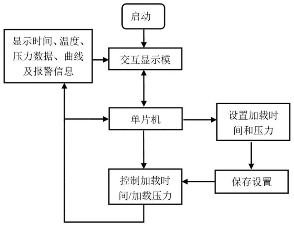
[0007] The existing air compressor loading device does not have an independent control system, and the loading time and pressure cannot be conveniently set according to different test requirements, and the dynamic curve and display alarm of temperature and pressure cannot be performed.

Method used


Image

  • Automatic control air compressor loading system
  • Automatic control air compressor loading system

Examples


Embodiment approach

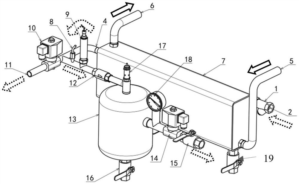
[0056] As an optimized embodiment of the present invention: the water inlet 5 of the cooling water tank 7 and the air inlet 1 of the cooling pipe 3 are on the same side wall of the cooling water tank 7 . Preferably, the water outlet 6 of the cooling water tank 7 is located at the top of the cooling water tank 7 . Preferably, a drain valve 19 is provided at the bottom of the cooling water tank 7 .

[0057] For the buffer tank 13, the present invention adopts various schemes to optimize it: a check valve 12 is provided between the inlet of the buffer tank 13 and the outlet pipeline. A safety valve 17 is provided at the air inlet of the buffer tank 13 . The inlet of the back pressure solenoid valve 14 is connected to the buffer tank 13, the outlet is connected to the inlet of the throttle valve 15, and the outlet of the throttle valve 15 is connected to the outside world. A pressure gauge 18 is provided between the back pressure solenoid valve 14 and the buffer tank 13 . A dra...


PUM


Abstract

The invention discloses an automatic control air compressor loading system which comprises a cooling water tank and a cooling pipe arranged in the cooling water tank. An air inlet of the cooling pipe is connected with the air compressor, and an air outlet is connected with loading equipment; the control equipment controls the loading pressure and the loading time of the loading equipment; the loading equipment comprises a pressure relief opening and a buffer tank; an air outlet of the cooling pipe is communicated with the pressure relief opening and the buffer tank through an air outlet pipeline; a loading electromagnetic valve for controlling the opening and closing of the pressure relief opening is arranged at the pressure relief opening; a pressure sensor is arranged on the air outlet pipeline; the backpressure electromagnetic valve is communicated with the side wall of the buffer tank through a pipeline; and the loading electromagnetic valve, the pressure sensor and the backpressure electromagnetic valve are electrically connected with control equipment. According to the invention, the volume is small, the temperature of cooled compressed air is about 50 DEG C, so that a test control system can work stably and reliably for a long time, and meanwhile, the backpressure control mode can be adjusted, so that the loading pressure test requirements of multi-model engine air compressors of 8bar, 10bar, 12.5 bar and the like can be met.

Description

technical field [0001] The invention mainly relates to a loading device and an automatic control system for multi-model air compressors in an engine test. Background technique [0002] Chinese patent "A loading device for air compressor in engine bench test", publication number CN207850693U, authorized announcement date 2018.09.11, discloses a loading device for air compressor in engine bench test, including air storage tank and The pipeline and control valve connected to the air compressor, the pipeline and control valve connected to the air compressor include a first pipeline connected to the air outlet of the air compressor, and the first pipeline is connected to the air storage tank through the second pipeline The air inlet is connected, the first solenoid valve and the one-way valve are connected in series on the second pipeline; the first pipeline is also connected to the exhaust pipe through the third pipeline, and the second solenoid valve is connected in series on t...

Claims


Application Information

Patent Timeline
Patent Type & Authority Applications(China)
IPC IPC(8): F04B51/00
CPCF04B51/00
Inventor 杨键王谦董锋肖美费明德
Owner DONGFENG COMML VEHICLE CO LTD
Learn More