
Smelting furnace with waste heat utilization structure for aluminum profile production and operation method thereof

An aluminum profile and smelting furnace technology, which is applied in the field of smelting furnaces with waste heat usable structure for aluminum profile production, can solve the problems of instability, pollute the ecological environment, and cannot be heated by other devices, and achieves improved stability and smooth transportation. Effect

Inactive Publication Date: 2022-03-15
肖竞赛
View PDF0 Cites 0 Cited by
  • Summary
  • Abstract
  • Description
  • Claims
  • Application Information

AI Technical Summary

Problems solved by technology

[0003] 1. In the process of conveying the waste heat of exhaust gas, because there are a lot of impurities in the waste heat of waste gas, it often leads to the situation that the impurities block the transportation pipeline during the transportation process.
[0004] 2. In the exhaust gas waste heat storage device, due to the instability of the waste gas waste heat, the stability of the storage device becomes low, resulting in the failure of the waste gas waste heat to be well preserved
[0005] 3. The waste heat cannot be well utilized, and other devices cannot be heated, resulting in the waste heat not being well utilized
[0006] 4. The exhaust gas discharged at the end is not well filtered, resulting in a large amount of impurities, which greatly pollutes the ecological environment

Method used


Image

  • Smelting furnace with waste heat utilization structure for aluminum profile production and operation method thereof
  • Smelting furnace with waste heat utilization structure for aluminum profile production and operation method thereof
  • Smelting furnace with waste heat utilization structure for aluminum profile production and operation method thereof

Examples


Embodiment Construction

[0041]The following will clearly and completely describe the technical solutions in the embodiments of the present invention with reference to the accompanying drawings in the embodiments of the present invention. Obviously, the described embodiments are only some, not all, embodiments of the present invention. Based on the embodiments of the present invention, all other embodiments obtained by persons of ordinary skill in the art without making creative efforts belong to the protection scope of the present invention.

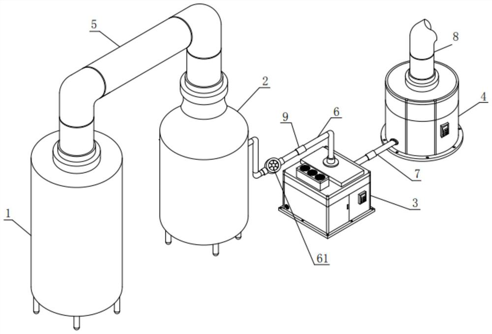
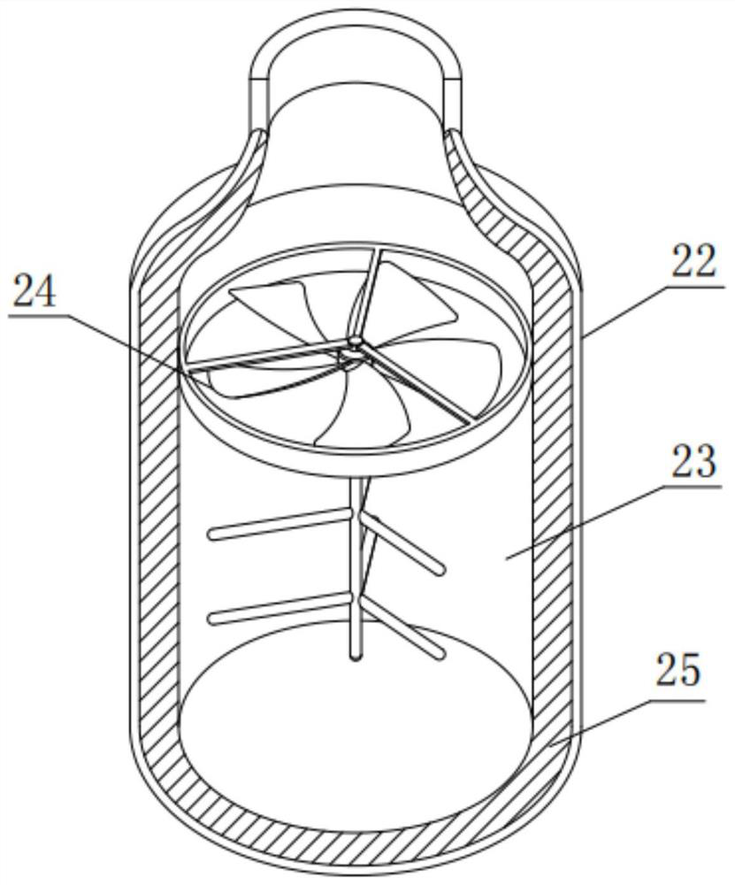
[0042] see Figure 1-8 , a smelting furnace with a waste heat utilization structure for the production of aluminum profiles, including a material furnace body 1, a first filter furnace body 2, a filter box 3 and a waste heat generation furnace 4, wherein the material furnace body 1 and the first filter furnace body 2 pass through The first pipeline 5 is connected, the first filter furnace body 2 and the filter box 3 are connected through the first gas pipeline ...


PUM


Abstract

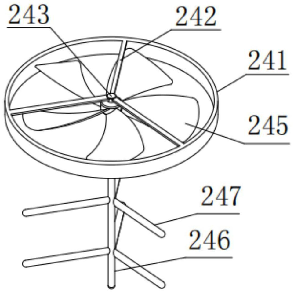
The invention discloses an aluminum profile production smelting furnace with a waste heat available structure and an operation method thereof, the aluminum profile production smelting furnace comprises a material furnace body, a first filtering furnace body, a filtering box body and a waste heat generation furnace, the material furnace body and the first filtering furnace body are connected through a first pipeline, and the first filtering furnace body and the filtering box body are connected through a first gas pipeline. The buffer stirrer can impact and buffer waste heat of waste gas in the inner cavity of the first filtering furnace body, so that the waste heat of the waste gas in the inner cavity of the first filtering furnace body is more uniform, the condition of conveying blockage is avoided, the transportation is smoother, the first filtering furnace body can play a better buffer role due to the elasticity, and the service life of the first filtering furnace body is prolonged. The stability performance of the first filtering furnace body is improved, the upper filtering plate and the lower filtering plate are used for final filtering, a vibrator can vibrate out redundant impurities in waste gas through vibration, the waste gas does not have impurities and pollution any more through multiple filtering, and air pollution cannot be caused.

Description

technical field [0001] The invention relates to the technical field of waste heat utilization, in particular to a smelting furnace with a waste heat utilization structure for the production of aluminum profiles and an operation method thereof. Background technique [0002] The melting furnace refers to the equipment that melts metal ingots and some scrap metals and adds necessary alloy components, and smelts them into the required alloys through operations such as slag removal and refining. The waste heat and exhaust gas produced by the existing smelting furnaces for the production of aluminum profiles cannot be well utilized, so the following problems often occur: [0003] 1. During the transportation of exhaust gas waste heat, because there are a lot of impurities in the exhaust gas waste heat, it often leads to the situation that the impurities block the transportation pipeline during the transportation process. [0004] 2. In the exhaust gas waste heat storage device, d...

Claims


Application Information

Patent Timeline
Patent Type & Authority Applications(China)
IPC IPC(8): F27B14/00F27B14/08F27D17/00
CPCF27B14/00F27B14/08F27D17/004F27D17/008F27M2001/012F27M2003/13Y02P10/25
Inventor 肖竞赛
Owner 肖竞赛
Learn More