
High-frequency vibration mode identification method and system based on motion amplification and digital image correlation

A motion amplification, digital image technology, applied in image communication, TV system parts, color TV parts and other directions, can solve the problems of inconvenient installation, low positioning accuracy, slow testing process, etc., to broaden the applicable frequency range , avoid damage accumulation, shorten the effect of test time

Active Publication Date: 2022-03-15
XIAN AEROSPACE PROPULSION INST
View PDF6 Cites 0 Cited by
  • Summary
  • Abstract
  • Description
  • Claims
  • Application Information

AI Technical Summary

Problems solved by technology

[0007] In order to solve the technical problems of the existing pipeline vibration test methods or the inconvenient installation, low positioning accuracy, which affect the test results; or the slow test process and low efficiency; or the low accuracy of the high-order vibration test, the present invention provides a High frequency mode shape recognition method and system based on motion amplification and digital image correlation

Method used


Image

  • High-frequency vibration mode identification method and system based on motion amplification and digital image correlation
  • High-frequency vibration mode identification method and system based on motion amplification and digital image correlation
  • High-frequency vibration mode identification method and system based on motion amplification and digital image correlation

Examples


Embodiment Construction

[0052] The content of the present invention will be further described in detail below in conjunction with the accompanying drawings and specific embodiments.

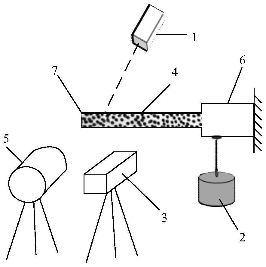
[0053] Such asfigure 1 As shown, the present invention is a high-frequency mode shape recognition system based on motion amplification and digital image correlation, including a laser Doppler vibrometer 1, an excitation device, a vibration pickup unit, a high-speed camera 3, an operational amplification unit and a DIC processing unit, The vibration pickup unit, operational amplification unit and DIC processing unit are not shown in the figure;

[0054] The vibration excitation device is used to apply an excitation signal and a fixed-frequency sinusoidal excitation to the tested structural member 7; The excitation may also include a hammer, through which a pulse excitation signal is applied to the tested structural member 7 , and a fixed-frequency sinusoidal excitation is applied through the vibrator 2 to the tested stru...


PUM


Abstract

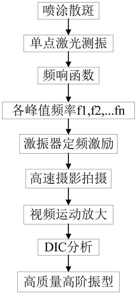
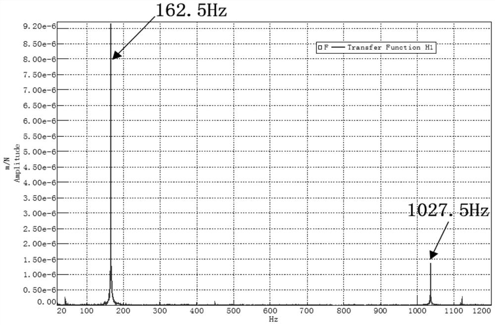
The invention provides a high-frequency vibration mode identification method and system based on motion amplification and digital image correlation, and solves the problems that an existing vibration mode test mode is inconvenient to install and low in positioning precision; the test process is slow and low in efficiency; and the high-order vibration mode test accuracy is low. The method comprises the following steps: 1) fixing a measured structural member and spraying speckles on the surface of the measured structural member; 2) arranging a laser Doppler vibration meter on the outer side of the measured structural member; 3) applying an excitation signal to the measured structural member, and triggering the laser Doppler vibration meter to acquire a response speed signal of the measured structural member; 4) processing the excitation signal and the response speed signal by adopting an estimation method to obtain a frequency response function, and finding out outburst frequency points from the frequency response function and representing the outburst frequency points as f1, f2,..., fn; (5) sine excitation signals with the fixed frequencies of f1, f2... fn are applied to the measured structural component, and meanwhile, a shot video under each sine excitation is shot; (6) motion amplification is carried out on each shot segment of the shot video; and 7) performing DIC analysis on the photographic video after motion amplification to obtain a high-frequency vibration mode.

Description

technical field [0001] The invention belongs to the technical field of modal testing, and in particular relates to a high-frequency mode shape recognition method and system based on motion amplification and digital image correlation, which is suitable for high-order mode shape recognition of light pipelines and thin-walled structures. Background technique [0002] In the liquid rocket engine, due to the existence of oscillating combustion excitation, fluid excitation and acoustic resonance, there is excitation energy in a wide frequency range inside the liquid rocket engine. In the actual working process of the liquid rocket engine, if the frequency of the pipeline is coupled with the internal excitation frequency of the liquid rocket engine, the pipeline will resonate, resulting in fatigue failure of the pipeline in a short time. In order to avoid the fatigue damage of the pipeline during the engine working process, it is necessary to test the high-order mode shape of the p...

Claims


Application Information

Patent Timeline
IPC IPC(8): G01H9/00H04N5/247
CPCG01H9/00H04N23/90Y02T90/00
Inventor 闫松张志伟薛杰赵瑞国张留欢王珺刘子俊
Owner XIAN AEROSPACE PROPULSION INST
Learn More