
Hybrid DC power transmission line single-end fault distance measurement method and system

A fault location and transmission line technology, applied in the fault location and other directions, can solve the problem of inaccurate location of the fault location method, and achieve the effects of reliable ranging results, high precision, strong adaptability and robustness

Active Publication Date: 2022-03-15
KUNMING UNIV OF SCI & TECH
View PDF4 Cites 1 Cited by
  • Summary
  • Abstract
  • Description
  • Claims
  • Application Information

AI Technical Summary

Problems solved by technology

[0004] The technical problem to be solved by the present invention is to provide a hybrid direct current transmission line single-end fault location method and system to solve the problem of inaccurate positioning of existing hybrid direct current transmission line fault location methods

Method used


Image

  • Hybrid DC power transmission line single-end fault distance measurement method and system
  • Hybrid DC power transmission line single-end fault distance measurement method and system
  • Hybrid DC power transmission line single-end fault distance measurement method and system

Examples


Embodiment 1

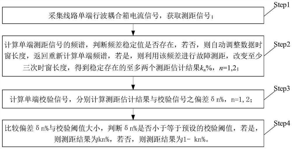
[0083] Embodiment 1: as figure 1 As shown, a hybrid DC transmission line single-ended fault location method, the specific steps are:

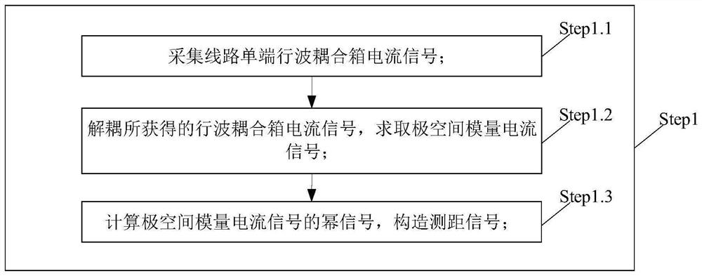
[0084] Step1: Collect the current signal of the line single-ended traveling wave coupling box to obtain the ranging signal, such as figure 2 shown, including steps.

[0085] Step1.1: Collect the current signal of the line single-ended traveling wave coupling box.

[0086] Step1.2: Decoupling the obtained current signal of the traveling wave coupling box to obtain the polar space modulus current signal.

[0087] Step1.3: Calculate the power signal of the polar space modulus current signal, and construct the ranging signal.

[0088] The power signal refers to performing an odd power transformation on the polar space modulus current signal.

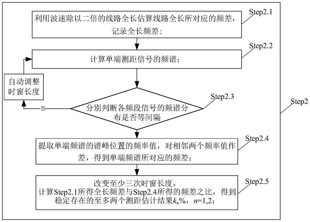
[0089] Step2: Calculate the spectrum of the single-ended ranging signal, and judge whether the stable value of the frequency difference exists. If not, automatically adjust the length of the data time wi...

Embodiment 2

[0140] Embodiment 2, assuming that a bipolar metallic short-circuit fault occurs at a distance of 300km from the M end, the sampling rate is 200kHz, and the distance measurement is carried out with the method of the present invention, and the specific steps are:

[0141] Step1: Collect the current signal of the line single-ended traveling wave coupling box to obtain the ranging signal. The specific steps are:

[0142] Step1.1: Collect the current signal of the line single-ended traveling wave coupling box i M ,Such as Figure 9 shown.

[0143] Step1.2: Calculate signal i M The third power signal of is used to construct the ranging signal.

[0144] The power signal refers to performing an odd power transformation on the polar space modulus current signal.

[0145] Step2: Calculate the spectrum of the single-ended ranging signal, and judge whether the stable value of the frequency difference exists. If not, automatically adjust the length of the data time window, and return ...

Embodiment 3

[0159] Embodiment 3: Assume that a bipolar metallic short-circuit fault occurs at a distance of 300 km from the M terminal, and the sampling rate is 200 kHz. The specific implementation steps of using the N-terminal single-ended data on the inverter side to realize ranging are as follows:

[0160] Step1: Collect the current signal of the line single-ended traveling wave coupling box to obtain the ranging signal. The specific steps are:

[0161] Step1.1: Collect the current signal of the line single-ended traveling wave coupling box i N ,Such as Figure 12 shown.

[0162] Step1.2: Calculate signal i N The third power signal of is used to construct the ranging signal.

[0163] The power signal refers to performing an odd power transformation on the polar space modulus current signal.

[0164] Step2: Calculate the spectrum of the single-ended ranging signal, and judge whether the stable value of the frequency difference exists. If not, automatically adjust the length of the ...


PUM


Abstract

The invention relates to a hybrid direct current transmission line single-end fault distance measurement method and system, and belongs to the technical field of power system relay protection control. The method comprises the following steps: collecting a line single-end traveling wave coupling box current signal to obtain a ranging signal; calculating the frequency spectrum of a single-end ranging signal, judging whether a frequency difference stable value exists or not, if not, automatically adjusting the length of a data time window, returning to recalculate the single-end frequency spectrum, and if yes, performing fault ranging by using the frequency difference and changing the length of the time window for at least three times to obtain at most two ranging estimation results kn% which exist stably, n = 1, 2; calculating a single-end verification signal, and respectively calculating the deviation delta n% between the distance measurement estimation result and the verification signal, n = 1, 2; the deviation delta n% is compared with a verification threshold value, whether delta n% is smaller than or equal to a preset verification threshold value or not is judged, if yes, the distance measurement result is kn%, and if not, the distance measurement result is 1-kn%. The method is suitable for various complex working conditions of the hybrid direct current system, the distance measurement result is high in accuracy, high in reliability and high in robustness.

Description

technical field [0001] The invention relates to a method and system for single-end fault distance measurement of a hybrid direct current transmission line, belonging to the technical field of relay protection control of a power system. Background technique [0002] Due to its advantages in long-distance large-capacity power transmission and grid interconnection, the proportion of high-voltage direct current (HVDC) in long-distance power transmission projects is increasing year by year. The traditional high-voltage direct current transmission (LCC-HVDC) technology based on phase-controlled converters has matured. It has the advantages of large transmission capacity, low cost, and mature operation technology. Therefore, the phase-controlled converter (LCC) is an important means to solve the problem of long-distance power transmission and grid interconnection. However, when LCC is used as an inverter, there are the following problems: first, there is a risk of commutation fail...

Claims


Application Information

Patent Timeline
IPC IPC(8): G01R31/08
CPCG01R31/08Y04S10/52
Inventor 束洪春安娜杨竞及韩一鸣唐玉涛代月单节杉曹璞璘董俊田鑫萃张广斌
Owner KUNMING UNIV OF SCI & TECH
Learn More