Intelligent equipment for automatically adjusting welding angle of steel pipe for industrial production line
A technology of automatic adjustment and welding angle, applied in welding equipment, auxiliary welding equipment, welding/cutting auxiliary equipment, etc., can solve the problems of reduced welding strength, unfavorable steel pipe welding, and welding holes, etc., and achieve the effect of solving welding strength.
- Summary
- Abstract
- Description
- Claims
- Application Information
AI Technical Summary
Problems solved by technology
Method used
Image
Examples
Embodiment 1
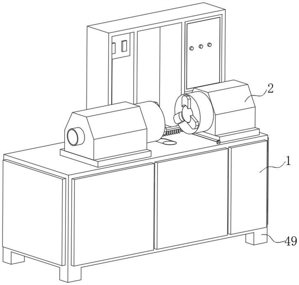
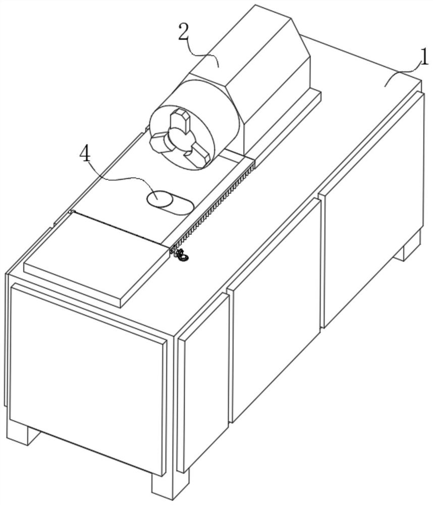
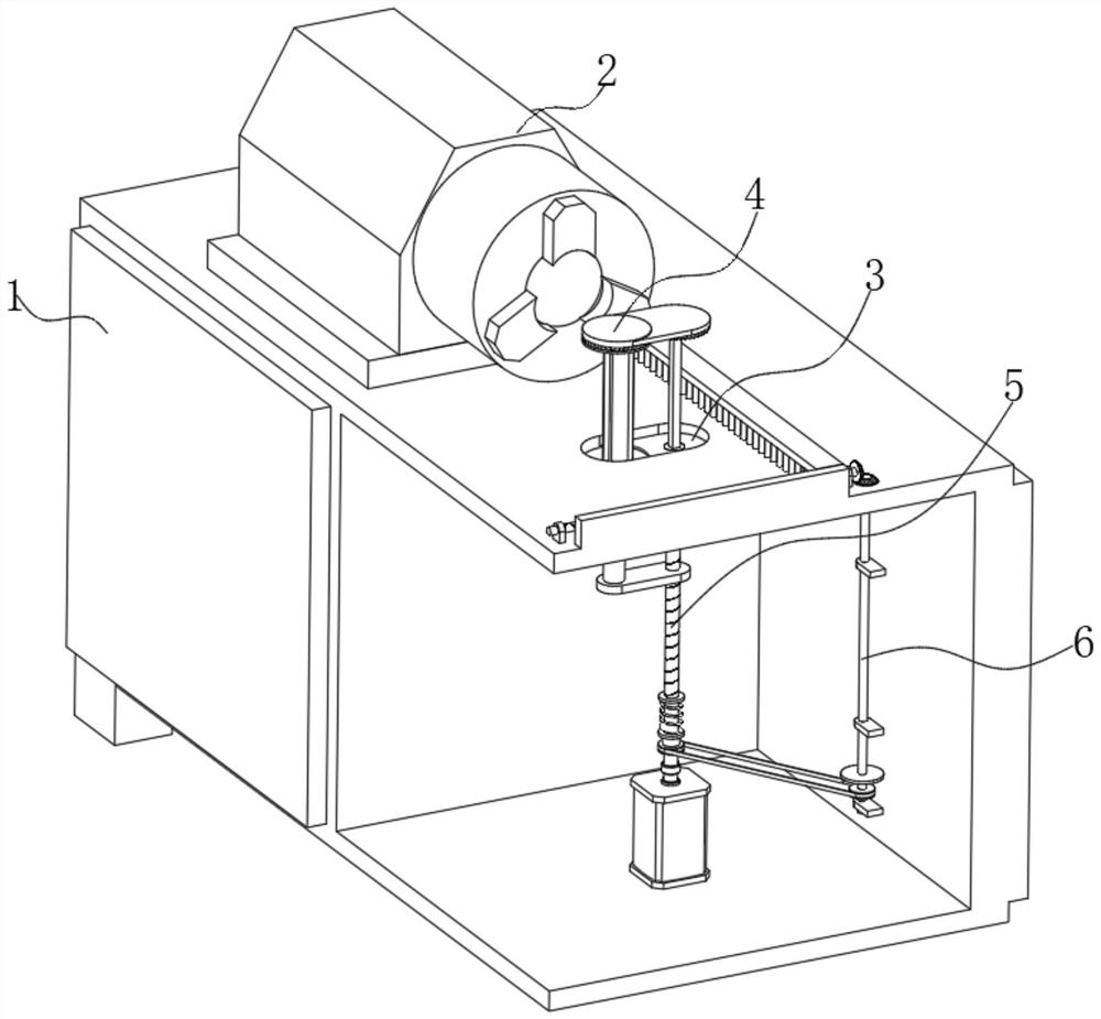
[0028] see Figure 1-Figure 3 Illustrate embodiment 1, a kind of industrial production line in the figure is used for automatically adjusting the intelligent equipment of steel pipe welding angle, comprises automatic welding machine body 1, moving assembly 5 and cleaning assembly 6, and automatic welding machine body 1 is provided with two groups for The fixed head 2 for fixing the steel pipe, and the top is located directly below the two groups of fixed heads 2, and a groove 3 is opened, and a cleaning sheet 4 is movably connected in the groove 3, and the moving assembly 5 for moving the cleaning sheet 4 is installed on the In the automatic welding machine body 1, and connected with the cleaning sheet 4, the cleaning assembly 6 for cleaning the impurities under the cleaning sheet 4 is installed in the automatic welding machine body 1, and connected with the moving assembly 5;
[0029] see image 3 with Figure 4 , the mobile assembly 5 in the illustration includes a motor 7...
Embodiment 2
[0037] see Figure 4 , Figure 7 with Figure 8 Example 2 is described. This embodiment will further explain Example 1. In the figure, the cleaning assembly 6 includes a cleaning brush 30 that is slidably connected to the main body 1 of the automatic welding machine and a stopper 22 that is connected to the connecting shaft 11. Cleaning The brush 30 is fixedly connected with a threaded block 31, the threaded block 31 is threadedly connected with a reciprocating screw rod 32, and both ends of the reciprocating screw rod 32 are rotatably connected with a first fixed seat 33 fixedly connected with the automatic welding machine body 1, and the reciprocating One end of the screw rod 32 is connected with a transmission member 34 connected with the drive shaft 9;
[0038] see Figure 4 with Figure 7 , the limiting member 22 in the illustration includes a movable piece 27 that is movably connected with the connecting shaft 11, and one end of the movable piece 27 is fixedly connec...
Embodiment 3
[0042] see Figure 4 , Figure 8 with Figure 9 Embodiment 3 is described. This embodiment will further illustrate Embodiment 2. In the figure, the transmission part 34 includes a driving wheel 35 fixedly connected to the drive shaft 9. The outer side of the driving wheel 35 is connected to a belt 36, and one end of the belt 36 is driven. A driven wheel 37 is connected, and the position of the axis of the driven wheel 37 is fixedly connected with a rotating shaft 38 connected to the automatic welding machine body 1 in rotation. 40, the transmission shaft 40 is rotatably connected with the second fixed seat 41 fixedly connected with the automatic welding machine body 1, the top end of the transmission shaft 40 is fixedly connected with the first bevel gear 42, and the outer side of the first bevel gear 42 is meshed with a reciprocating wire The second bevel gear 43 fixedly connected to the rod 32;
[0043] see Figure 8 and with Figure 9 , the rotation limiting member 39 ...
PUM
 Abstract
Description
Claims
Application Information
 - R&D
- Intellectual Property
- Life Sciences
- Materials
- Tech Scout
- Unparalleled Data Quality
- Higher Quality Content
- 60% Fewer Hallucinations
Browse by: Latest US Patents, China's latest patents, Technical Efficacy Thesaurus, Application Domain, Technology Topic, Popular Technical Reports.
© 2025 PatSnap. All rights reserved.Legal|Privacy policy|Modern Slavery Act Transparency Statement|Sitemap|About US| Contact US: help@patsnap.com


