Laser ray spacing measurement method for robot self-calibration

A measurement method and self-calibration technology, applied in the field of robot calibration, can solve the problems of low efficiency and achieve high efficiency and wide application

Pending Publication Date: 2022-03-18
CHANGCHUN UNIV OF SCI & TECH
View PDF0 Cites 0 Cited by
  • Summary
  • Abstract
  • Description
  • Claims
  • Application Information

AI Technical Summary

Problems solved by technology

[0004] In order to solve the problem of low efficiency in the laser spot coordinate measurement method in the prior art, the present invention proposes a laser beam distance measurement m

Method used


Image

  • Laser ray spacing measurement method for robot self-calibration
  • Laser ray spacing measurement method for robot self-calibration
  • Laser ray spacing measurement method for robot self-calibration

Examples


Embodiment Construction

[0049] The present invention will be described in further detail below in conjunction with the accompanying drawings.

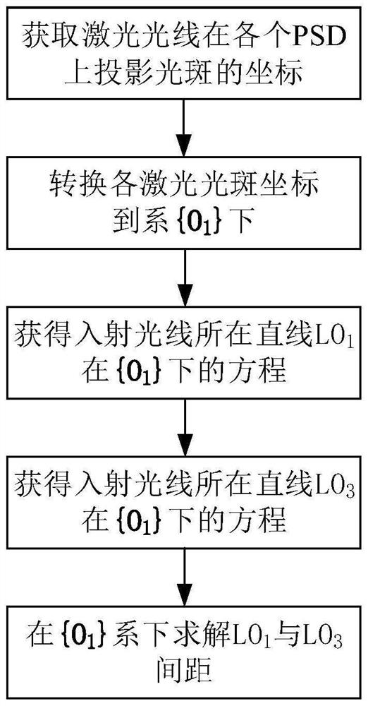
[0050] Laser beam distance measurement method for robot self-calibration, such as figure 1 shown, including the following steps:

[0051] Step 1. Obtain the coordinates of the laser light spot projected on each PSD

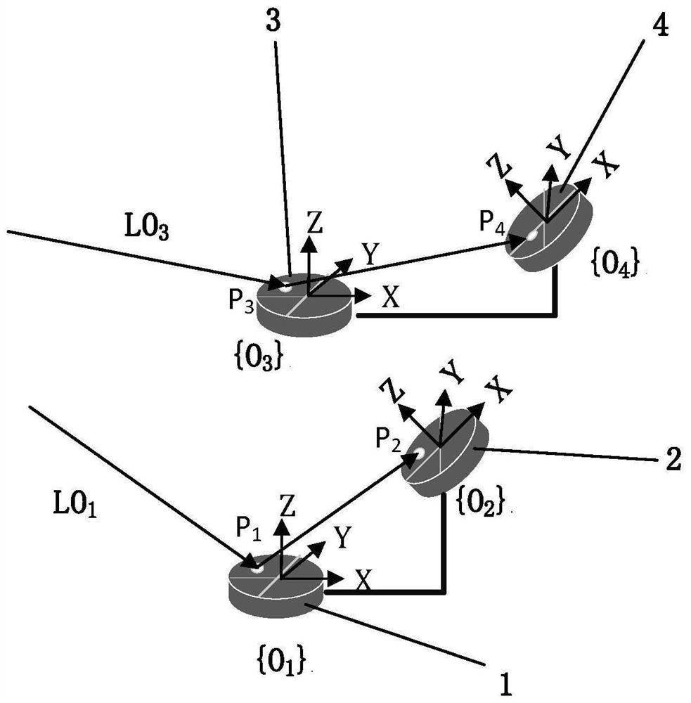
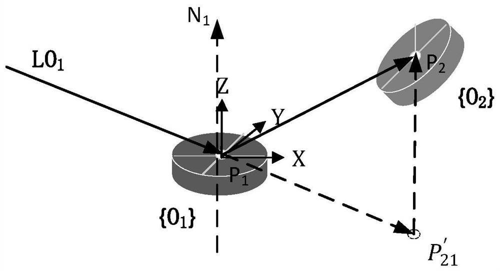
[0052] Such as figure 2 As shown, let the PSD 1 1 The coordinate system is {O 1}, PSD 2 2 The coordinate system is {O 2}, PSD 3 3 coordinate system is {O 3}, PSD 4 4 The coordinate system is {O 4}, {O 1}, {O 2}, {O 3}, {O 4} rigidly fixed together. Department {O 2} relative to the system {O 1}’s pose transformation matrix is Department {O 3} relative to the system {O 1}’s pose transformation matrix is Department {O 4} relative to the system {O 1}’s pose transformation matrix is is known; make the laser light LO 1 via PSD 1 1 center area reflection to PSD 2 2 central area, at this time incident to the system {O 1} Th...


PUM


Abstract

The invention discloses a laser ray spacing measurement method for robot self-calibration, relates to the technical field of robot calibration, in particular to a robot closed-loop kinematic chain establishment method for robot self-calibration, and aims to solve the problem of low efficiency of a laser spot coordinate measurement method in the prior art. According to the laser ray spacing measurement method for robot self-calibration, four PSDs are adopted as laser ray constraints, laser spots are aligned with the central areas of the PSDs, and laser ray spacing measurement is completed. The invention relates to a laser ray spacing measurement method for robot self-calibration. The method comprises the following steps: step 1, obtaining coordinates of projection light spots of laser rays on each PSD; step 2, converting the coordinates of each laser spot to a system {O1}; step 3, obtaining an equation of a straight line LO1 where the incident light is located under a system {O1}; step 4, obtaining an equation of a straight line LO3 where the incident light is located under a system {O1}; and step 5, solving the spacing between LO1 and LO3 under the system {O1}.

Description

technical field [0001] The invention relates to the technical field of robot calibration, in particular to a method for measuring laser beam distances for robot self-calibration. Background technique [0002] The absolute positioning accuracy of industrial robots is low due to the manufacturing accuracy of the manipulator components, the assembly and installation of the manipulator components, the error between the reference coordinate system and the actual coordinate system, the non-parallel axis error, and the kinematic parameters of the manipulator. Among them, the kinematic parameters of the mechanical arm have the greatest influence, so it is necessary to calibrate the kinematic parameters of the industrial robot. At present, the absolute positioning error of the end of the robot is accurately measured by third-party measurement equipment for calibration. Although the accuracy is high, it is expensive and complicated to operate. [0003] Chinese Patent Publication No. ...

Claims


Application Information

Patent Timeline
IPC IPC(8): B25J9/16
CPCB25J9/1653
Inventor 苏成志姜丰包海峰王浪
Owner CHANGCHUN UNIV OF SCI & TECH
Why Eureka
Try Eureka