Ground stress direction determination method and device, storage medium and computer equipment

A technology for determining the method and stress direction, applied in geophysical measurement, instrumentation, climate sustainability, etc., can solve the problems of difficult to draw clear regional geological conditions, lack of continuity, small amount of data, etc., to achieve optimized well trajectory , Strong practicability and high precision

Pending Publication Date: 2022-03-18
CHINA PETROLEUM & CHEM CORP +1
View PDF0 Cites 2 Cited by
  • Summary
  • Abstract
  • Description
  • Claims
  • Application Information

AI Technical Summary

Problems solved by technology

1. The direct measurement method, using instruments to measure the in-situ stress is relatively accurate, but the amount of data is too small, the cost is high, and lacks continuity, so it is not suitable for obtaining large-scale in-situ stress data; 2. Acoustic-electric imaging logging data Evaluation method, the difficulty of this method is that for formations with little difference in stress intensity, it is difficult to obtain the characteristics of response stress deformation from the acoustic-electric image, such as induced fractures; 3. Numerical simulation method, numerical simulation of stress distribution is mostly based on measured data Based on the topography and geological characteristics, the model is established for inversion back calculation and simulation. The difficulty is that it is difficult to understand the regional geological conditions, and single well data is also required as a constraint; 4. Earthquake prediction method, the difficulty of the method lies in It is necessary to consider the influence of tectonic stress, pore pressure and other parameters on the in-situ stress

Method used


Image

  • Ground stress direction determination method and device, storage medium and computer equipment
  • Ground stress direction determination method and device, storage medium and computer equipment
  • Ground stress direction determination method and device, storage medium and computer equipment

Examples


Embodiment 1

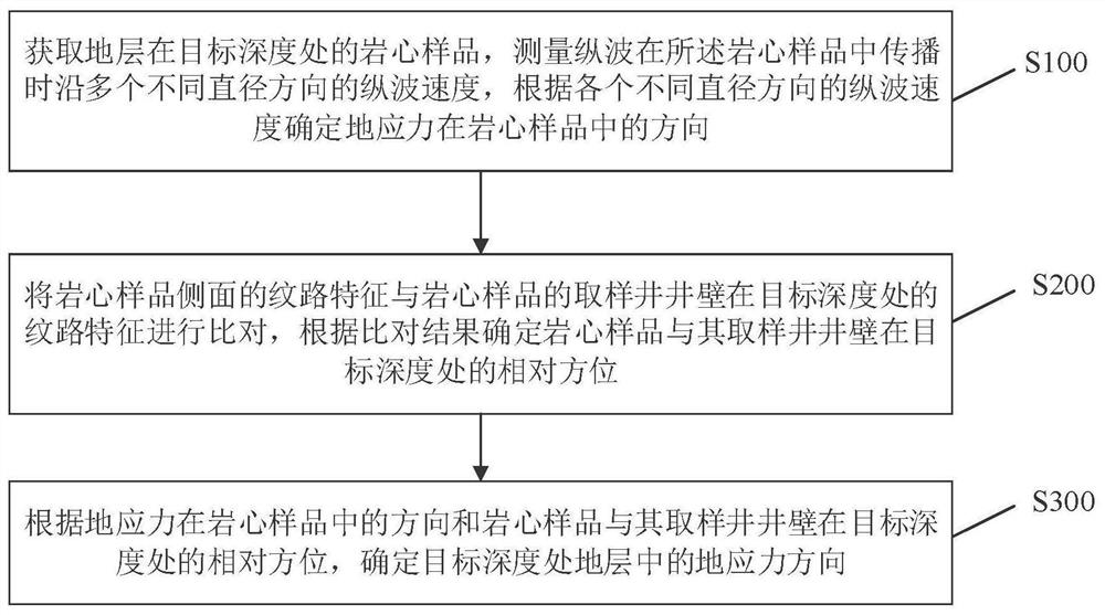
[0028] figure 1 It is a flowchart of a method for determining the direction of ground stress according to an exemplary embodiment of the present application. Such as figure 1 As shown, the present embodiment provides a method for determining the direction of in-situ stress, comprising the following steps:

[0029] S100: Obtain a core sample of the formation at the target depth, measure the longitudinal wave velocity along multiple different diameter directions when the longitudinal wave propagates in the core sample, and determine the direction of the in-situ stress in the core sample according to the longitudinal wave velocity in each different diameter direction;

[0030] S200: comparing the texture features on the side of the core sample with the texture features of the core sample's sampling well wall at the target depth, and determining the relative orientation of the core sample and the sampling well wall at the target depth according to the comparison result;

[0031]...

Embodiment 2

[0033] This embodiment provides a method for determining the direction of ground stress, comprising the following steps:

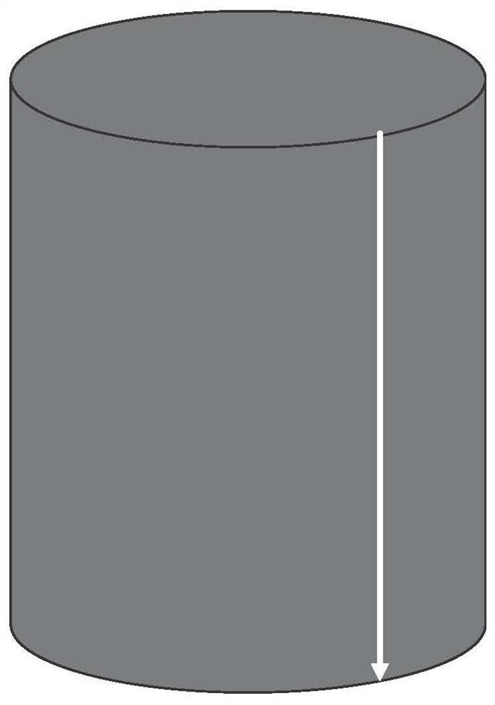
[0034] Step 1: Obtain a rock core sample of the formation at the target depth, and set a reference line parallel to the axial direction of the rock core sample on the side of the rock core sample, wherein the rock core sample is cylindrical, and the rock core sample can be a full-diameter core sample .

[0035] The second step: measure the longitudinal wave velocity along multiple different diameter directions when the longitudinal wave propagates in the rock core sample, and determine the direction of the in-situ stress in the rock core sample according to the longitudinal wave velocity in each different diameter direction. Specifically, the in-situ stress in the rock core sample can be determined. The direction in is relative to the central angle of the reference line, and the central angle is used to describe the direction of the geostress in the core s...

Embodiment 3

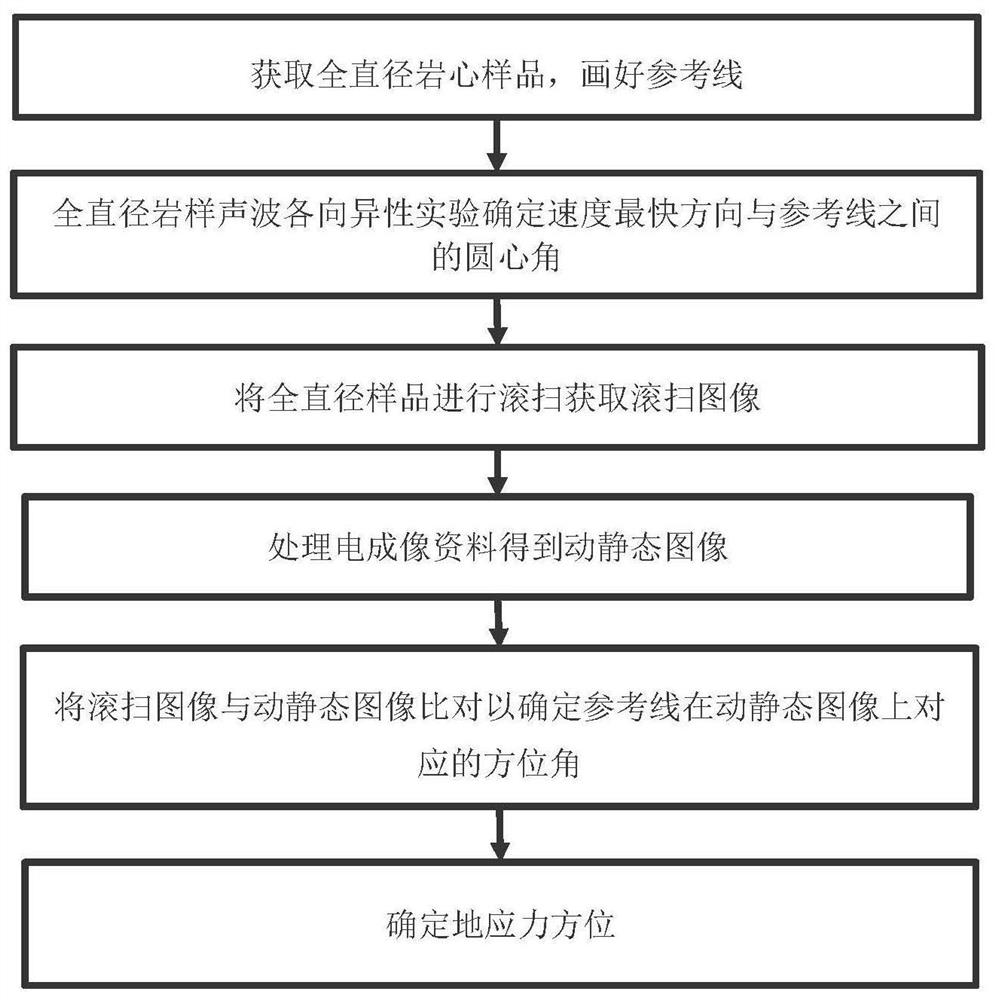
[0043] figure 2 It is a flowchart of a method for determining the direction of ground stress according to a specific embodiment of the present application. Such as figure 2 As shown, the method for determining the direction of in-situ stress includes the following steps:

[0044] S1: Obtain the full-diameter rock core sample of the formation at the target depth. The full-diameter rock core sample is cylindrical, and a reference line parallel to the axial direction of the full-diameter rock core sample is set on the side of the full-diameter rock core sample (such as Figure 3A with Figure 3B shown). in, Figure 3B The number mark in is the mark made by the mud logger after the core sample is taken out from the ground. The number in front of the fractional line indicates the number of cylinders, the denominator indicates how many core samples there are in total in the cylinder, and the numerator indicates the number of core samples in the current cylinder. Piece. Figu...


PUM


Abstract

The invention provides a ground stress direction determination method and device, a storage medium and computer equipment. The method comprises the following steps: acquiring a rock core sample of a stratum at a target depth, measuring longitudinal wave speeds of longitudinal waves in a plurality of different diameter directions when the longitudinal waves are propagated in the rock core sample, and determining the direction of ground stress in the rock core sample according to the longitudinal wave speeds in the different diameter directions; comparing the texture characteristics of the side surface of the rock core sample with the texture characteristics of the well wall of the sampling well of the rock core sample at the target depth, and determining the relative orientation of the rock core sample and the well wall of the sampling well at the target depth according to the comparison result; and according to the direction of the crustal stress in the core sample and the relative orientation of the core sample and the well wall of the sampling well at the target depth, determining the direction of the crustal stress in the stratum at the target depth. The method is strong in theoretical basis, can be used for ground stress direction judgment of various reservoirs, especially stratums with small plastic change, and is beneficial to optimization of well body tracks and reasonable arrangement of hydraulic fracturing directions.

Description

technical field [0001] The invention relates to the technical fields of petroleum geology and petroleum engineering, in particular to a method, device, storage medium and computer equipment for determining the direction of in-situ stress. Background technique [0002] In-situ stress plays an increasingly important role in petroleum exploration and development. In-situ stress is a key factor affecting the effect of fracturing. In oilfield reservoir stimulation, the state of stress field determines the shape, orientation, height and width of hydraulic fractures, which has an impact on the effect of fracturing stimulation; well pattern layout and adjustment in development need to study the stress field, Otherwise, the oil displacement efficiency may be reduced, the water-free oil recovery period may be shortened, and phenomena such as water channeling and water flooding may occur. Therefore, in-situ stress research based on formation characteristics is a necessary part of res...

Claims


Application Information

Patent Timeline
Patent Type & Authority Applications(China)
IPC IPC(8): G01V11/00
CPCG01V11/00Y02A90/30
Inventor 胡松熊平李军刘伟男邹友龙胡瑶刘密刘坤
Owner CHINA PETROLEUM & CHEM CORP
Why Eureka
Try Eureka