Hand bracket for assisting PICC (Peripherally Inserted Central Catheter) catheterization for coma patient

A technology of hand support and tube placement, which is applied in the field of hand support, which can solve the problems of wasting manpower, polluting the disinfection surface, increasing the workload of nursing, etc., and achieves the effects of saving manpower, facilitating storage, and reducing the workload of nursing

Pending Publication Date: 2022-03-22
THE FIRST AFFILIATED HOSPITAL OF ANHUI MEDICAL UNIV
View PDF0 Cites 1 Cited by
  • Summary
  • Abstract
  • Description
  • Claims
  • Application Information

AI Technical Summary

Problems solved by technology

[0003] Most of the comatose patients in the ICU cannot cooperate during the disinfection period, and the disinfection surface will be polluted due to weak support. A third person is required to help lift the patient's up

Method used


Image

  • Hand bracket for assisting PICC (Peripherally Inserted Central Catheter) catheterization for coma patient
  • Hand bracket for assisting PICC (Peripherally Inserted Central Catheter) catheterization for coma patient
  • Hand bracket for assisting PICC (Peripherally Inserted Central Catheter) catheterization for coma patient

Examples


Embodiment 1

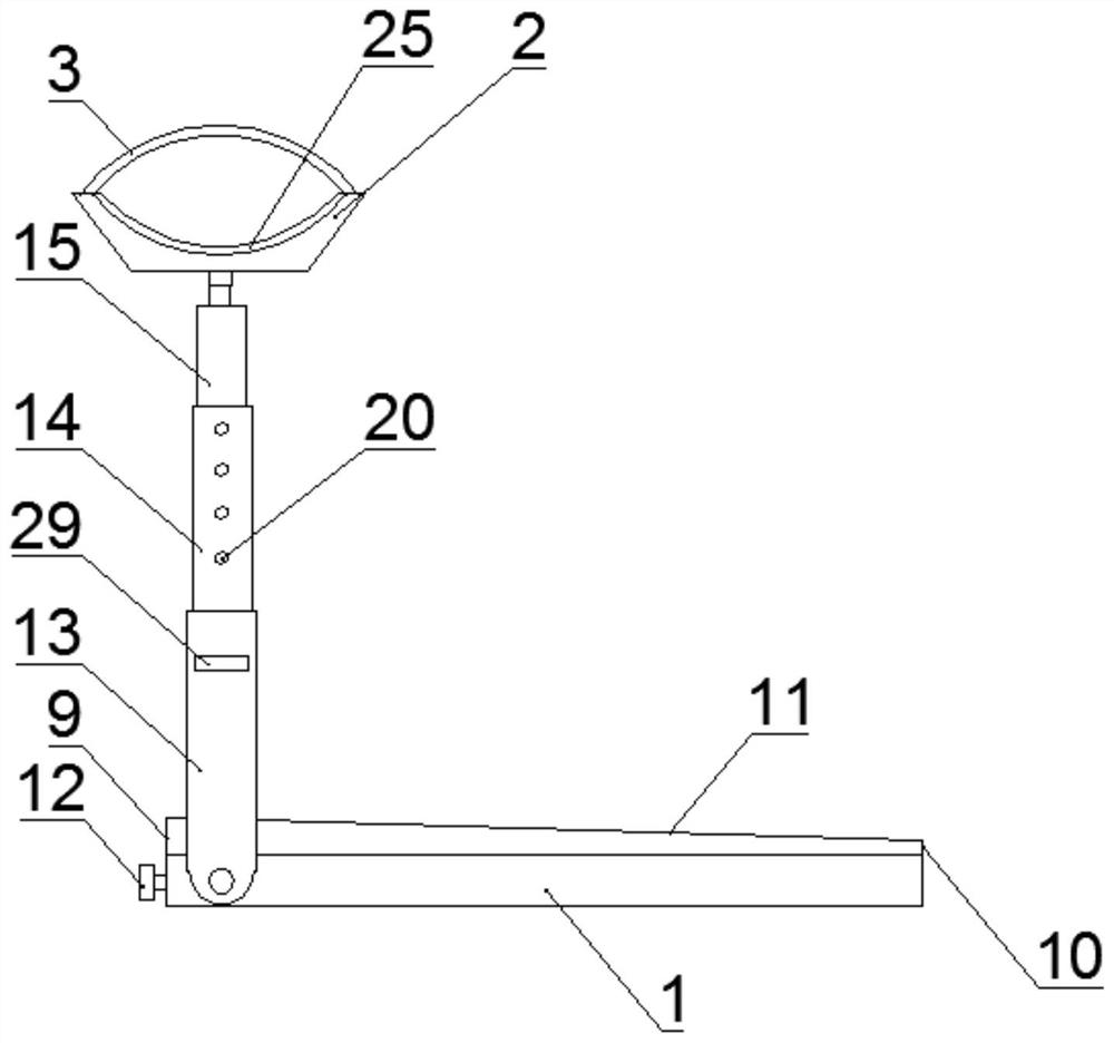
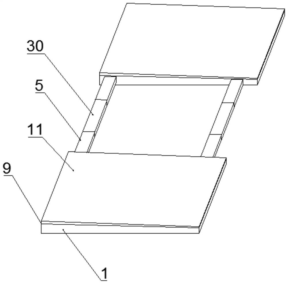
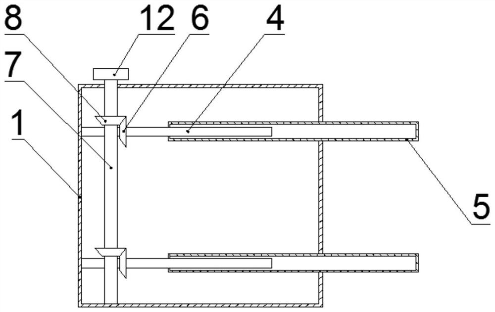
[0043] Embodiment one, refer to Figure 1-7 , the present application provides a bracket for assisting PICC tube placement in comatose patients. When in use, unfold the two folded base plates 1 so that the two base plates 1 are located on the same horizontal plane, insert the two base plates 1 between the hospital bed and the mattress, and rotate them manually The first knob 12, when the first knob 12 rotates, it drives the connected rotating rod 7 to rotate, and the rotating rod 7 drives the second bevel gear 8 to rotate, and the second bevel gear 8 drives the engaged first bevel gear 6 to rotate, so that the first threaded rod 4 Rotation drives the screw-connected support plate 5 to produce a displacement, thereby adjusting the distance between the two bottom plates 1. After the adjustment is completed, turn the hinged first support rod 13 to 90 degrees vertically, and the second thread that fixes the lower end of the bracket 2 The rod 24 is rotated and installed in the thre...

Embodiment 2

[0044] Embodiment two, refer to Figure 8-9 The difference between this embodiment and Embodiment 1 is that handles 31 are provided on opposite sides of the two bottom plates 1, and locking pieces are provided on the side of the bottom plates 1 away from the handles 31, and the two bottom plates 1 are limitedly matched by the locking pieces.

[0045] For further optimization, any bottom plate 1 is provided with a slide groove 32 on one side away from the handle 31, and the locking key includes a slide block 33 slidably connected in the slide groove 32, and a first spring 36 is arranged in the slide groove 32, and the first spring 36 One end is fixedly connected with the slider 33. The other end of the first spring 36 is fixedly connected with the inner wall of the chute 32 , the top of the slider 33 is hinged with a locking lever 34 , the top of the locking lever 34 is fixedly connected with a locking block 35 , and the other bottom plate 1 is provided with a locking groove 37...

Embodiment 3

[0048] Embodiment three, refer to Figure 10-11 The difference between the present embodiment and the second embodiment is that the bottom end of the base plate 1 is provided with a first base plate 38, and a through hole is provided on the first base plate 38, and a slide bar 39 is slidably connected in the through hole, and the top of the slide bar 39 is connected to the base plate. 1. The bottom end is fixedly connected, the bottom end of the slide bar 39 is hinged with a third threaded rod 40, the third threaded rod 40 is threaded with a nut 41, the bottom end of the first bottom plate 38 is provided with a groove, and the third threaded rod 40 is connected with the groove match.

[0049] In this embodiment, when in use, the third threaded rod 40 is taken out from the groove and rotated around the hinge point so that the third threaded rod 40 and the slide rod 39 are located on the same axis, and the first bottom plate 38 can slide up and down, so that the bed body of the ...


PUM


Abstract

The invention discloses a hand support for assisting PICC (Peripherally Inserted Central Catheter) catheterization for coma patients, which comprises two bottom plates, a first vertical plate and a second vertical plate are sequentially and fixedly connected to the bottom plates, a transverse plate is fixedly connected to the top ends of the first vertical plate and the second vertical plate, and the transverse plate, the first vertical plate and the second vertical plate form a right trapezoid. A telescopic folding mechanism is arranged between the two bottom plates, the two bottom plates are matched in a limiting mode through the telescopic folding mechanism, a supporting mechanism is hinged to the side, away from the telescopic folding mechanism, of any bottom plate, the supporting mechanism is located at the end, close to the first vertical plate, of the bottom plate, and a hand supporting frame is arranged at the top end of the supporting mechanism. The bottom end of the hand supporting frame is fixedly connected with a connecting mechanism, the hand supporting frame is detachably connected with the top end of the supporting mechanism through the connecting mechanism, and a restraint strap is arranged at the top end of the hand supporting frame. The device is simple in structure, low in cost and convenient to operate, store and carry.

Description

technical field [0001] The invention relates to the technical field of medical devices, in particular to a bracket for assisting PICC tube placement for comatose patients. Background technique [0002] Peripherally inserted central venous catheters (PICCs) have many advantages such as avoiding repeated venipuncture, relieving patients' pain, protecting blood vessels, being safe to use, and having a long indwelling time, and have been widely used clinically. Most of the patients in the ICU are critically ill patients with a large demand for fluid replacement and poor peripheral vascular conditions, so puncturing PICC catheters is particularly important. Strict aseptic operation should be performed when inserting the PICC tube. When disinfecting the arm, use a sterile cotton swab or cotton ball, dip it in iodine disinfectant, and use the needle insertion point as the center of the circle for disinfection. The range is more than 20 cm from the center of the circle, clockwise an...

Claims


Application Information

Patent Timeline
IPC IPC(8): A61G13/12
CPCA61G13/1235A61G13/124A61G13/1285
Inventor 方业香邵敏李落吾杜小玲汪艳红齐梦影
Owner THE FIRST AFFILIATED HOSPITAL OF ANHUI MEDICAL UNIV
Why Eureka
Try Eureka