Dryer automatic feeding conveying device with preliminary drying function

A conveying device and automatic feeding technology, applied in dryers, drying solid materials, drying gas layout, etc., can solve problems such as different drying times, tearing of raw materials, and affecting drying quality.

Active Publication Date: 2022-03-22
江苏德尔瑞环保机械有限公司
View PDF9 Cites 0 Cited by
  • Summary
  • Abstract
  • Description
  • Claims
  • Application Information

AI Technical Summary

Problems solved by technology

[0003] However, most of the existing raw materials that need to be dried are viscous. When feeding through the conveying device, the raw materials are easy to adhere to the surface of the conveying device, which affects the efficiency of loading and unloading. With the increase of surface fouling, it will even affect the stability of feeding sex
Most conveying devices can only transport raw materials, and in order to improve production efficiency and reduce enterprise costs, dryers often use non-stop feeding. Therefore, when new raw materials enter a high-temperature environment, due to the large instantaneous temperature difference, the water evaporates instantly. Increased air pressure will easily tear the raw material and affect the drying quality
[0004] In addition, the initial moisture content of most raw materials is different, so the drying time required is different. Raw materials with too much water content are dried within the rated drying time, which is likely to cause insufficient drying. Drying within the rated drying time will easily lead to over-drying, which also affects the drying quality, thereby affecting the drying efficiency of the dryer

Method used


Image

  • Dryer automatic feeding conveying device with preliminary drying function
  • Dryer automatic feeding conveying device with preliminary drying function
  • Dryer automatic feeding conveying device with preliminary drying function

Examples


Embodiment Construction

[0036] The following will clearly and completely describe the technical solutions in the embodiments of the present invention with reference to the accompanying drawings in the embodiments of the present invention. Obviously, the described embodiments are only some, not all, embodiments of the present invention. Based on the embodiments of the present invention, all other embodiments obtained by persons of ordinary skill in the art without making creative efforts belong to the protection scope of the present invention.

[0037] The invention provides technical solutions:

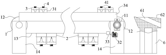
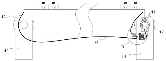
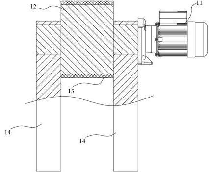
[0038] Such as Figure 1~Figure 8 As shown, the conveying device for the automatic feeding of the dryer with the preliminary drying function includes a power device 1, a carrying device 2, a flow guide device 3 and an adjustment device 4, the power device 1 and the carrying device 2 are connected by transmission, and the flow guide device 3 It communicates with the carrying device 2, the power device 1 is f...


PUM


Abstract

The invention discloses a drying machine automatic feeding conveying device with a preliminary drying function, which comprises a power device, a bearing device, a flow guide device and an adjusting device, the power device is in transmission connection with the bearing device, the flow guide device is communicated with the bearing device, the power device is in fastening connection with the flow guide device, and the adjusting device is connected with the bearing device. The guiding device is connected with the adjusting device, the power device comprises a driving motor, transmission wheels and a conveying belt, the two transmission wheels are arranged on the inner ring of the conveying belt and are in transmission connection with the conveying belt, supports are arranged on the two sides of the two transmission wheels respectively, the transmission wheels are rotationally connected with the supports, and the moving direction of the upper side of the conveying belt is the feeding direction. The driving motor is located on one side of the support at the front end of the feeding direction, the output end of the driving motor is in transmission connection with the transmission wheel at the front end of the feeding direction, the drying strength of raw materials is adjusted through the adjusting device, the humidity of the raw materials is made to be at a small threshold value, and the drying quality is guaranteed.

Description

technical field [0001] The invention relates to the technical field of dryer conveying devices, in particular to a conveying device for automatic feeding of dryers with a preliminary drying function. Background technique [0002] Dryers are mostly used for dehydration of raw materials. They are divided into various dehydration forms. Drying through thermal drying is still the main method. Thermal drying is beneficial for enterprises to control costs. [0003] However, most of the existing raw materials that need to be dried are viscous. When feeding through the conveying device, the raw materials are easy to adhere to the surface of the conveying device, which affects the efficiency of loading and unloading. As the surface scale increases, it will even affect the stability of feeding sex. Most conveying devices can only transport raw materials, and in order to improve production efficiency and reduce enterprise costs, dryers often use non-stop feeding. Therefore, when new r...

Claims


Application Information

Patent Timeline
IPC IPC(8): B65G15/30B65G23/04B65G23/22F26B17/04F26B21/00F26B23/06F26B25/22
CPCB65G15/30B65G23/04B65G23/22F26B17/04F26B21/004F26B23/06F26B25/002F26B25/22
Inventor 朱万才
Owner 江苏德尔瑞环保机械有限公司
Why Eureka
Try Eureka