Heat treatment device for high-performance iron-based amorphous nanocrystalline strip
A technology of nanocrystalline strip and heat treatment device, applied in heat treatment furnace, heat treatment equipment, heat treatment process control and other directions, can solve problems such as low efficiency and labor consumption, and achieve the effect of enhancing flexibility, improving efficiency, and homogenizing stress state.
- Summary
- Abstract
- Description
- Claims
- Application Information
AI Technical Summary
Problems solved by technology
Method used
Image
Examples
Embodiment 1
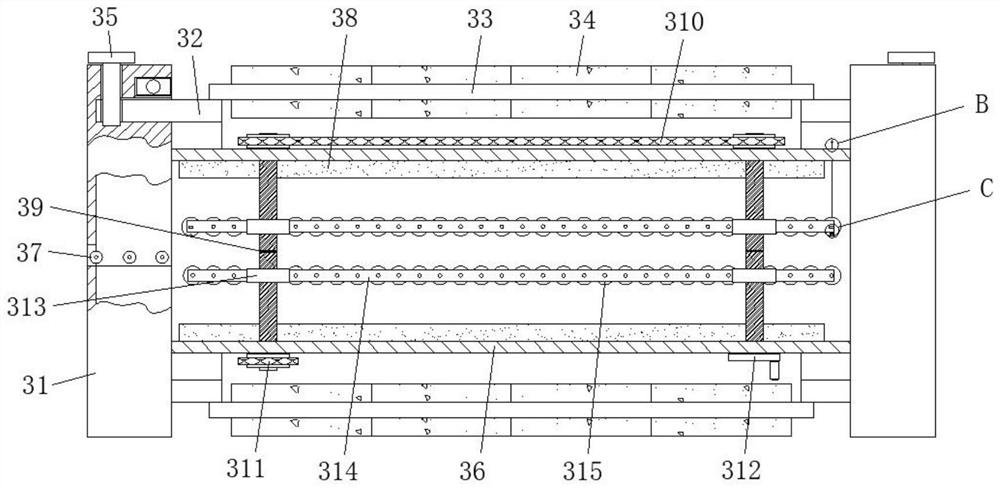
[0037] refer to Figure 1-4A heat treatment device for a high-performance iron-based amorphous nanocrystalline strip, comprising an unwinding mechanism 1 and a winding mechanism 2, a primary heat treatment mechanism 3 and a condensation treatment mechanism 4 are arranged between the unwinding mechanism 1 and the winding mechanism 2 and the secondary heat treatment mechanism 5, by being provided with three temperature treatment chambers, the temperature can be conveniently raised and lowered during the heat treatment of the amorphous and nanocrystalline strips, thereby greatly increasing the heating and cooling speed in the heat treatment box 36, and then greatly improving the non-crystalline The efficiency of crystal nanocrystalline strip processing, the primary heat treatment mechanism 3 includes two fixed seats 31 arranged horizontally, and the two fixed seats 31 are provided with cylindrical holes at one end close to each other. The outer wall of the upper and lower ends of...
Embodiment 2
[0039] Such as figure 1 , 2 , 8 and 9, the present embodiment is basically the same as Embodiment 1. Preferably, the unwinding mechanism 1 includes a support base 101, and the upper ends of the two support bases 101 are connected to a flip bar 102 for rotation damping, and the front and rear outer walls of the flip bar 102 are uniform. A vertical plate 103 is fixed, and a winding rod 104 is installed between the two vertical plates 103 in the same group. The outer wall of the winding rod 104 is fixed with a nano-strip roll 105. The end of the vertical plate 103 facing away from the turning rod 102 is provided with a U-shaped Groove, winding rod 104 and vertical plate 103 are fixedly connected with latch one 106, and support base 101 is provided with two and is symmetrically distributed in the rear side position of working face, and vertical plate 103 is provided with four and is two groups of symmetrical distributions. The upper and lower end positions of the turning rod 102,...
Embodiment 3
[0042] Such as figure 2 and 7 As shown, this embodiment is basically the same as Embodiment 1. Preferably, the output end of the drive motor 9 is fixed with a rectangular sleeve 10, the inner wall of the rectangular sleeve 10 is rotatably connected to a connecting plate 11, and the connecting plate 11 is opened at one end away from the rectangular sleeve 10. There is a groove, and the winding rod 104 on the winding mechanism 2 passes through the rear side of the vertical plate 103 and extends into the groove, and a latch 3 12 is connected between the connecting plate 11 and the winding rod 104 .
[0043] In this embodiment, the connecting plate 11 and the winding rod 104 are fixed by the bolt 3 12, which is convenient to disassemble and assemble, thus providing a certain guarantee for the efficient replacement and installation of the large nano-strip roll 105, thereby greatly improving the performance of the amorphous nano-strip roll 105. The efficiency of continuous winding...
PUM
 Abstract
Description
Claims
Application Information
 - R&D
- Intellectual Property
- Life Sciences
- Materials
- Tech Scout
- Unparalleled Data Quality
- Higher Quality Content
- 60% Fewer Hallucinations
Browse by: Latest US Patents, China's latest patents, Technical Efficacy Thesaurus, Application Domain, Technology Topic, Popular Technical Reports.
© 2025 PatSnap. All rights reserved.Legal|Privacy policy|Modern Slavery Act Transparency Statement|Sitemap|About US| Contact US: help@patsnap.com


