Five-axis corner characteristic efficient machining tool path generation method

A corner and tool path technology, used in instruments, digital control, control/regulation systems, etc., can solve problems such as large changes in cutting allowance, complex programming, and chattering of machining systems, optimize cutting conditions, and reduce tool wear. , to avoid the effect of the knife letting the knife

Active Publication Date: 2022-03-22
CHENGDU AIRCRAFT INDUSTRY GROUP
View PDF24 Cites 1 Cited by
  • Summary
  • Abstract
  • Description
  • Claims
  • Application Information

AI Technical Summary

Problems solved by technology

[0006] The purpose of the present invention is to solve the problems of large variation of cutting allowance, large cutting force, chattering of the machining system, etc. in the numerical control machining process of the corner characteristics of the groove cavity of the aeronautical structural parts, and the problems of low machining efficiency and complicated programming of the traditional method. A method for generating tool paths for efficient machining of five-axis corner features is proposed, which can effectively reduce the cutting force and tool clearance during five-axis corner machining, improve machining efficiency, and avoid parts quality problems

Method used


Image

  • Five-axis corner characteristic efficient machining tool path generation method
  • Five-axis corner characteristic efficient machining tool path generation method
  • Five-axis corner characteristic efficient machining tool path generation method

Examples


example 1

[0060] Material species of processing workpieces: aluminum alloy;

[0061] Machine tool performance: five coordinate high-speed gantry machine, spindle maximum speed 24000R / min, use speed 9000R / min;

[0062] Tool cutting performance: 2 teeth 2, diameter is 10mm;

[0063] Maximum equivalent cut: 3mm;

example 2

[0065] Material species of processing workpieces: aluminum alloy;

[0066] Machine tool performance: five coordinate high-speed gantry machine, spindle maximum speed 24000R / min, use speed 20000R / min;

[0067] Tool cutting performance: The number of teeth is 2, a diameter is 16mm;

[0068] Maximum equivalent cut: 5mm;

example 3

[0070] Material Type of Processing Workpapers: Titanium Alloy;

[0071] Machine tool performance: five coordinate high-speed gantry machine, spindle maximum speed 6000R / min, use 2400R / min;

[0072] Tool cutting performance: number of teeth is 4, diameter is 10mm;

[0073] Maximum equivalent cut: 1mm.

[0074] This embodiment is implemented using the data of the above example 1.

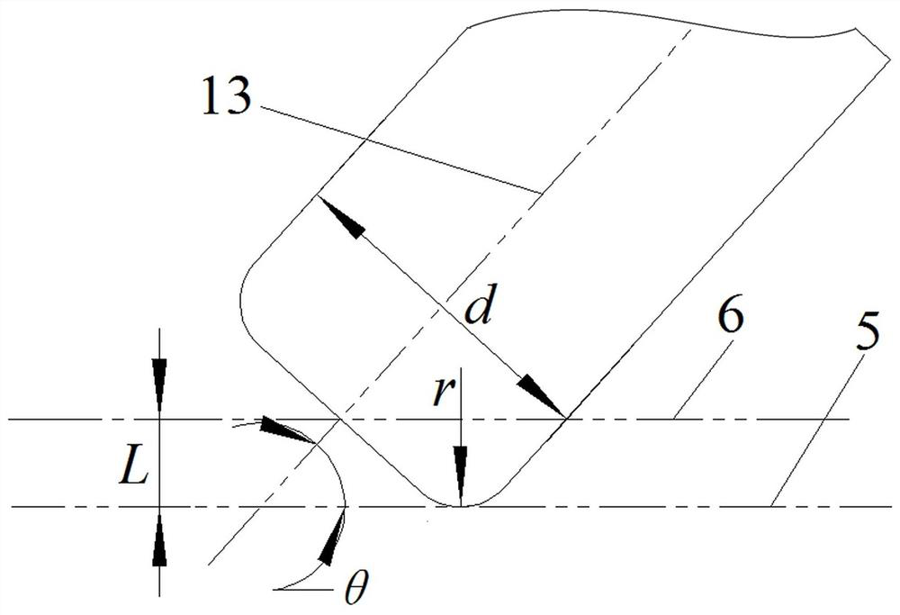
[0075] S4, set the tool diameter and bottom angle radius, calculate the deviation value of each layer of the five-axis corner to each layer of the five-axis angle, and create an equivalent bottom surface 6; specifically, such as figure 2 As shown, the offset value between the equivalent bottom surface 6 and the cut bottom surface 5 of each layer , In which the tool diameter D = 10mm, the bottom angle radius r = 3mm, the angle of the cutter shaft 13 and the cut bottom surface 5 θ = 75.22 °, calculate L = 0.427mm.

[0076] S5, intersecting point 8 with the equivalent bottom surface 6 of the corner surf...


PUM


Abstract

The invention relates to the field of numerical control machining of parts, in particular to a five-axis corner characteristic efficient machining tool path generation method. The cutting state optimization of five-axis corner machining is realized by controlling the cutter shaft vector and the equivalent cutting width of the cutter during five-axis corner machining. Firstly, a cutter axis vector is calculated according to the corner side face, and then the tool path driving geometry of the five-axis corner is obtained according to tool geometric parameters, the corner depth and the axial cutting depth; the maximum equivalent cutting width of a current tool is determined according to the machining tool performance and the machining tool information, and a machining tool path with the five-axis corner characteristic in the groove cavity is generated through a cyclic machining strategy. The five-axis corner machining tool path can be suitable for machining of various five-axis corners with the side faces being planes or equivalent planes, and the machining quality of the corners can be effectively improved.

Description

Technical field [0001] The present invention relates to CNC machining of parts, and more particularly, to a five-axis machining tool path angle characteristic efficient generation. Background technique [0002] In recent years, demands for improvement of equipment performance aerospace, and overall, lightweight, aerospace structural member cavity large number of grooves for reducing the weight of the parts, while ensuring the stiffness and strength of the corner features as the flute chambers mutually wherein the side transitional connections, is an important part of the groove chamber, two sides not only to avoid the drawbacks connected directly formed edge region can not be processed, but also eliminate the stress concentration. Corner feature present in the NC machining the cutting margin changes, cutting power, such as lack of processing systems flutter. At the same time due to the large cutting margin changes, prone to make knives knife, knife bomb in the corner processing, ...

Claims


Application Information

Patent Timeline
Patent Type & Authority Applications(China)
IPC IPC(8): G05B19/19
CPCG05B19/19G05B2219/35321
Inventor 王鹏程牟文平高鑫沈昕彭雨王斌利李卫东李仁政
Owner CHENGDU AIRCRAFT INDUSTRY GROUP
Why Eureka
Try Eureka