
A device and method for precise positioning of passive RFID tags

An RFID tag and precise positioning technology, applied in the direction of cooperative operation devices, record carriers used by machines, advanced technology, etc., can solve the problems of unable to drive passive RFID tags, unable to query and locate in batches, and unable to use passive, etc., to achieve The effect of simple design, high positioning accuracy and strong adaptability

Active Publication Date: 2022-06-07
SHANDONG HUAYI MICRO ELECTRONICS
View PDF12 Cites 0 Cited by
  • Summary
  • Abstract
  • Description
  • Claims
  • Application Information

AI Technical Summary

Problems solved by technology

[0008] Chinese patent document CN113030860A discloses a method for positioning by the color, brightness and duration of the light emitted by the RFID positioning tag, but the tag requires a built-in battery, so it cannot be used for passive RFID
Although this document uses radio frequency to identify items in the area, when the LED is used for RFID tag object identification and flashing prompts, it is realized by the card reader controlling an additional wireless communication module. Due to power problems, it cannot be directly detected by passive RFID tags. drive
[0011] In addition, combined with the analysis of the above patent documents, it can be seen that the positioning of RFID requires the support of database management and wireless network communication, and the cost is relatively high; and only one specified tag can be operated at a time, and batch query and positioning cannot be performed.

Method used


Image

  • A device and method for precise positioning of passive RFID tags
  • A device and method for precise positioning of passive RFID tags
  • A device and method for precise positioning of passive RFID tags

Examples


Embodiment 1

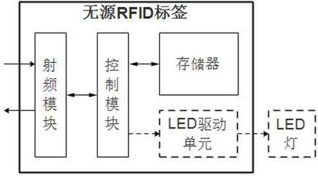
[0065] like figure 2 As shown, a precise positioning device for a passive RFID tag includes: a passive RFID tag and an external LED light, the passive RFID tag includes a radio frequency module, a control module, a memory and an LED driving unit;

[0066] The radio frequency module is used for wireless radio frequency communication with the reader; the control module is used to parse the LED control instructions with screening parameters sent by the reader and respond; the memory module is used to save the corresponding items. Identification information; the LED driving unit is used to drive the LED light on or off according to the response.

Embodiment 2

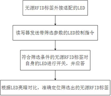
[0068] like figure 1 As shown, the positioning method using the precise positioning device of the passive RFID tag as described in Embodiment 1 includes:

[0069] (1) Externally adapted LED lights are attached to the passive RFID tag; the identification information of the corresponding item is recorded in the memory module in advance;

[0070] (2) Using the reader to send LED control instructions with screening parameters, the screening parameters include: instruction code (Code) part, LED control (Ctrl) part, comparison value (Value) part and action (Action) part;

[0071] The instruction code (Code) part is the instruction code of the LED control instruction; the LED control (Ctrl) part is used to control the LED to turn on or off: for example, 1 means on, 0 means off; the comparison value (Value) part uses When compared with the identification information: if they are the same, the identification information matches the LED control instruction; if not, the identification i...

Embodiment 3

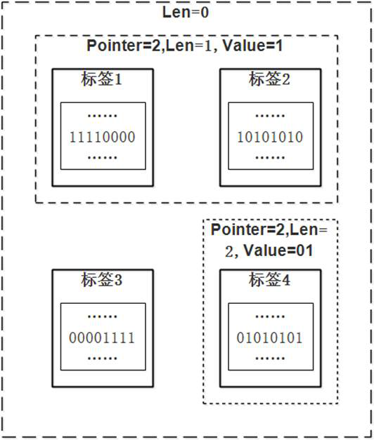
[0080] According to the positioning method according to Embodiment 2, the screening parameters further include: a starting address (Pointer) part and a data length (Len) part; the starting address (Pointer) part and the data length (Len) part are determined according to Identify the screening data in the information, and compare the screening data with the comparison value (Value) part:

[0081] If the same, the identification information matches the LED control instruction;

[0082] If not, the identification information does not match the LED control instruction.

[0083] In the step (3), the radio frequency module receives the LED control instruction, and the control module reads the identification information of the corresponding item in the memory module, and then performs data information matching.

[0084] When the data length (Len) part corresponding to the screening parameter in the LED control command is 0, it means that all passive RFID tags are screened by the LED...


PUM


Abstract

A device and method for precise positioning of a passive RFID tag, belonging to the technical field of RFID chip design, including: a passive RFID tag and an external LED light; the passive RFID tag includes a radio frequency module, a control module, a memory, and an LED driver unit; the radio frequency module is used for wireless radio frequency communication with the reader; the control module is used to analyze the LED control instruction with screening parameters sent by the reader and respond; the memory module is used to save the corresponding The identification information of the item; the LED drive unit is used to drive the LED light on or off according to the response. The invention has flexible design and simple logic control, avoids the problem that the wireless positioning is easily interfered by the environment, and simultaneously reduces hardware expenses such as extra time and area.

Description

technical field [0001] The invention discloses a precise positioning device and method for passive RFID tags, belonging to the technical field of RFID chip design. Background technique [0002] Radio frequency identification is radio frequency identification technology, English Radio Frequency Identification, RFID, is a kind of automatic identification technology, non-contact two-way data communication through radio frequency, using radio frequency to read the recording medium, that is, electronic tags or radio frequency cards Write, so as to achieve the purpose of identifying the target and data exchange. [0003] In the above identification system, the reading, writing and communication of electronic tags are realized through electromagnetic waves. According to the communication distance, it can be divided into near field and far field. For this reason, the data exchange method between the read / write device and the electronic tag is correspondingly divided into load modul...

Claims


Application Information

Patent Timeline
Patent Type & Authority Patents(China)
IPC IPC(8): G06K7/10G06K17/00G06K19/077
CPCG06K7/10099G06K17/0029G06K19/07705Y02D30/70
Inventor 韩英李向宏王伟刘文兵王丹单涛
Owner SHANDONG HUAYI MICRO ELECTRONICS
Learn More