
Automatic assembling mechanism for special-shaped sealing ring

A special-shaped sealing ring, automatic assembly technology, applied in the direction of measuring device, transportation and packaging, conveyor objects, etc., can solve the problems of difficult to control product quality, increase the probability of errors, increase labor intensity, etc., to achieve convenient operation and improve work. Efficiency, the effect of improving production efficiency

Pending Publication Date: 2022-03-25
昆山迈征自动化科技有限公司
View PDF8 Cites 1 Cited by
  • Summary
  • Abstract
  • Description
  • Claims
  • Application Information

AI Technical Summary

Problems solved by technology

[0003] The existing special-shaped sealing ring automatic assembly mechanism has certain disadvantages in use. First, the special-shaped sealing ring is manually installed. Due to the large size of the sealing ring and the overall strength is relatively soft, the sealing ring needs to be pressed into the O-ring groove during the installation process. Internally, the installation process is time-consuming and laborious, and the work efficiency is low, which is not conducive to people's use. In addition, the manufacturing process requires frequent participation of workers, which not only increases labor intensity, but also increases costs. Excessive manual participation also increases errors. Probability makes the product quality more difficult to control, and brings certain adverse effects to people's use process. Therefore, we propose an automatic assembly mechanism for special-shaped sealing rings

Method used


Image

  • Automatic assembling mechanism for special-shaped sealing ring
  • Automatic assembling mechanism for special-shaped sealing ring
  • Automatic assembling mechanism for special-shaped sealing ring

Examples


Embodiment 1

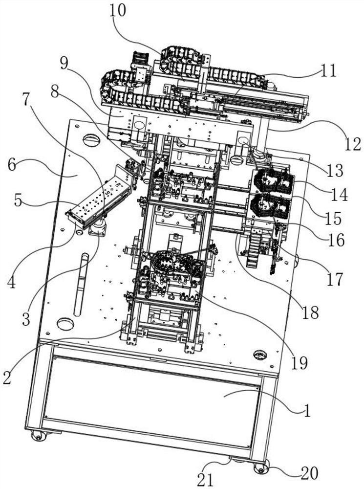
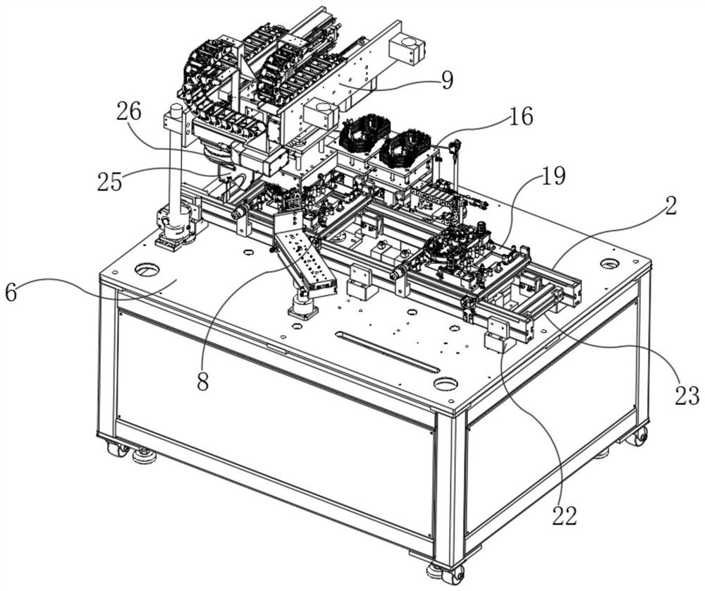
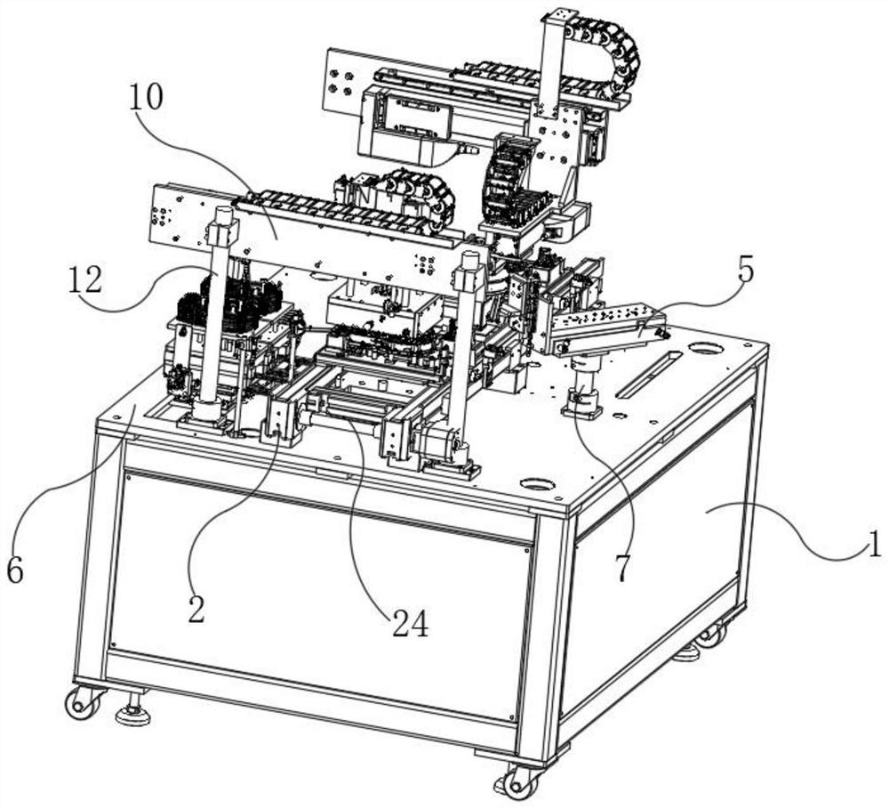
[0026] Such as Figure 1-4 As shown, a special-shaped sealing ring automatic assembly mechanism includes a processing table 1, a processing station 6 is installed on the upper end of the processing table 1, and an installation connection block 21 is installed on the bottom of the processing table 1, and the bottom of the installation connection block 21 is provided with a movable Roller 20, positioning support 3, column 12, drawer-type quick-change fixture 17 and servo module 2 are installed on processing station 6, and No. 1 feed bin 16 and No. 2 feed bin 15 are installed on drawer-type quick-change fixture 17.

[0027] Further, the upper end of the column 12 is equipped with a transport module 10, the transport module 10 is equipped with a slideway 11, the front end of the slideway 11 is equipped with a transport mechanism 9, and the front end of the transport mechanism 9 is equipped with a transport material folder 13, the servo mold The upper end of the group 2 is provided...

Embodiment 2

[0031] On the basis of Example 1, as Figure 1-4 As shown, a special-shaped sealing ring automatic assembly mechanism includes a processing table 1, a processing station 6 is installed on the upper end of the processing table 1, and an installation connection block 21 is installed on the bottom of the processing table 1, and the bottom of the installation connection block 21 is provided with a movable Roller 20, positioning support 3, column 12, drawer-type quick-change fixture 17 and servo module 2 are installed on processing station 6, and No. 1 feed bin 16 and No. 2 feed bin 15 are installed on drawer-type quick-change fixture 17.

[0032] Further, the upper end of the positioning support 3 is provided with a rotating shaft 7, the upper end of the rotating shaft 7 is equipped with a vacuum suction cup seat 5, and the outer side of the vacuum suction cup seat 5 is equipped with a positioning frame 4, and the servo module 2 and the drawer type quick-change fixture 17 Telescop...

Embodiment 3

[0035] On the basis of embodiment one and embodiment two, such as Figure 1-4As shown, a special-shaped sealing ring automatic assembly mechanism includes a processing table 1, a processing station 6 is installed on the upper end of the processing table 1, and an installation connection block 21 is installed on the bottom of the processing table 1, and the bottom of the installation connection block 21 is provided with a movable Roller 20, positioning support 3, column 12, drawer-type quick-change fixture 17 and servo module 2 are installed on processing station 6, and No. 1 feed bin 16 and No. 2 feed bin 15 are installed on drawer-type quick-change fixture 17.

[0036] Further, a connecting frame 23 is installed on the inner side of the servo module 2, a positioning connection card seat 22 is installed between the servo module 2 and the processing station 6, and a driving rod 24 is provided at both ends of the servo module 2, A camera detection mechanism 26 is installed on th...


PUM


Abstract

The automatic assembling mechanism for the special-shaped sealing ring comprises a machining table, a machining station is installed at the upper end of the machining table, an installation connecting block is installed at the bottom of the machining table, and movable rolling wheels are arranged at the bottom of the installation connecting block; a positioning support, a stand column, a drawer type quick-change clamp and a servo module are installed on the machining station, a first stock bin and a second stock bin are installed on the drawer type quick-change clamp, a carrying module is installed at the upper end of the stand column, a sliding way is installed on the carrying module, and a carrying mechanism is installed at the front end of the sliding way. According to the automatic assembling mechanism for the special-shaped sealing rings, the double stock bins can achieve non-stop feeding, the production efficiency is improved, different tools are interchanged to be compatible with various special-shaped sealing rings, the situation that the sealing rings are neglected to be assembled, too many sealing rings are assembled and not assembled in place can be prevented through CCD detection, the automatic technology of the special-shaped sealing rings is optimized, automation is achieved to the maximum degree, and the production efficiency is improved. And the working efficiency and the product yield are improved.

Description

technical field [0001] The invention relates to the field of automatic machinery, in particular to an automatic assembly mechanism for special-shaped sealing rings. Background technique [0002] The automatic assembly mechanism for special-shaped sealing rings is a supporting device for detecting and assembling sealing rings. Modern development has higher and higher requirements for the automation level of the manufacturing industry. In the field of new energy automatic assembly and manufacturing technology, manual assembly of special-shaped sealing rings requires It consumes a lot of labor. With the continuous development of science and technology, people have higher and higher requirements for the manufacturing process of the special-shaped sealing ring automatic assembly mechanism. [0003] The existing special-shaped sealing ring automatic assembly mechanism has certain disadvantages in use. First, the special-shaped sealing ring is manually installed. Due to the large s...

Claims


Application Information

Patent Timeline
Patent Type & Authority Applications(China)
IPC IPC(8): B23P19/00B65G47/06B65G47/91G01B21/02G01N21/84
CPCB23P19/004B65G47/915B65G47/06G01B21/02G01N21/84
Inventor 蔺新峰
Owner 昆山迈征自动化科技有限公司
Learn More