
Cutting device with deburring structure for casting and forging machining

A cutting device and deburring technology, which is applied in the field of casting and forging processing, can solve the problems of personnel burns, reducing the efficiency of casting and forging processing, and not having a grinding mechanism, so as to avoid burns, improve the effect of grinding, and improve efficiency.

Inactive Publication Date: 2022-03-25
徐州东创重工机械有限公司
View PDF0 Cites 0 Cited by
  • Summary
  • Abstract
  • Description
  • Claims
  • Application Information

AI Technical Summary

Problems solved by technology

[0002] The casting and forging cutting device is mainly based on laser cutting. Laser cutting uses a focused high-power density laser beam to irradiate the workpiece, so that the irradiated material is rapidly melted, vaporized or reaches the ignition point, and at the same time, it is blown away by the high-speed airflow coaxial with the beam. It is one of the thermal cutting methods to cut the workpiece by melting the material, so as to realize the cutting of the workpiece. However, there are too many burrs on the surface of the casting and forging, so it is necessary to improve the structure of the cutting device of the casting and forging.
[0003] In the process of realizing the present invention, the inventor found that at least the following problems in the prior art have not been solved: the existing casting and forging cutting device does not have a grinding mechanism, so after the casting and forging is cut, the casting and forging is cut out for grinding. burr, which greatly reduces the efficiency of casting and forging processing, and the casting and forging needs to be turned manually when grinding the burr, which not only reduces the efficiency of grinding and deburring, but also the high temperature of the polished casting and forging can easily cause burns to personnel. Therefore, we propose Cutting device with deburring structure for casting and forging processing

Method used


Image

  • Cutting device with deburring structure for casting and forging machining
  • Cutting device with deburring structure for casting and forging machining
  • Cutting device with deburring structure for casting and forging machining

Examples


Embodiment Construction

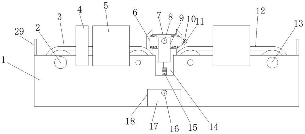
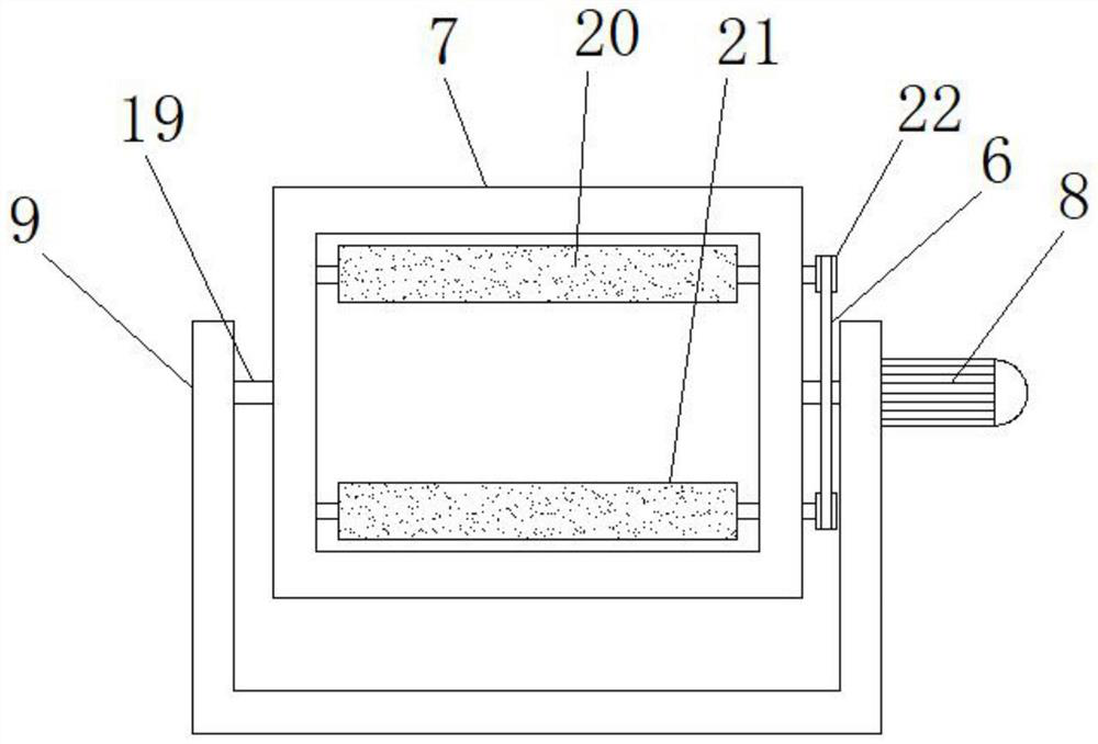
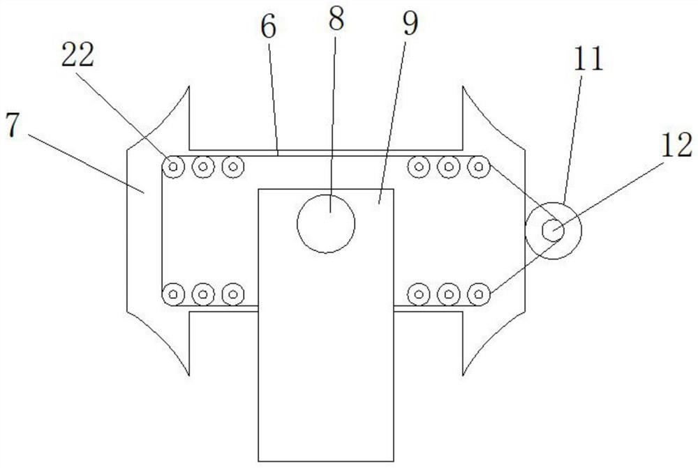
[0022] see Figure 1-5 , the present invention provides a technical solution: a cutting device with a deburring structure for casting and forging processing, including a processing table 1, the left and right ends of the inner cavity of the processing table 1 are respectively installed with a first belt conveyor 3 and a second belt conveyor. Two belt conveyors 12, the left and right sides of the front end of the processing table 1 are respectively fixedly equipped with a first drive motor 2 and a second drive motor 13, and the motor shafts of the first drive motor 2 and the second drive motor 13 are respectively connected to The first belt conveyor 3 is connected to the second belt conveyor 12, a laser cutting machine 4 is fixedly connected between the front and rear ends of the processing table 1, and a grinding frame 5 is installed on the left and right sides of the front end of the processing table 1 The two grinding frames 5 are respectively placed on the upper side of the...


PUM


Abstract

The invention relates to the technical field of casting and forging machining, and discloses a cutting device with a deburring structure for casting and forging machining. The cutting device comprises a machining table, and the left end and the right end of an inner cavity of the machining table are provided with a first belt conveyor and a second belt conveyor correspondingly; a first driving motor and a second driving motor are fixedly mounted on the left side and the right side of the front end of the machining table correspondingly. Through the arrangement of the first belt conveyor, the second belt conveyor, the push rod motor, the third driving motor, the fourth driving motor, the overturning frame, a chain, a driving chain wheel, a driven chain wheel, a conveying roller, a spring, a telescopic rod, a grinding belt, a driving roller and a fifth driving motor, the deburring efficiency is improved; and the situation that workers are scalded due to the high temperature of the polished casting and forging pieces is avoided, the polishing belt and the casting and forging pieces can be tightly attached through cooperation of a spring and a telescopic rod, and therefore the casting and forging piece polishing effect is improved, and meanwhile the casting and forging pieces with different thicknesses can be deburred.

Description

technical field [0001] The invention relates to the technical field of casting and forging processing, in particular to a cutting device with a deburring structure for casting and forging processing. Background technique [0002] The casting and forging cutting device is mainly based on laser cutting. Laser cutting uses a focused high-power density laser beam to irradiate the workpiece, so that the irradiated material is rapidly melted, vaporized or reaches the ignition point, and at the same time, it is blown away by the high-speed airflow coaxial with the beam. It is one of the thermal cutting methods to cut the workpiece by melting the material, so as to realize the cutting of the workpiece. However, there are too many burrs on the surface of the casting and forging, so it is necessary to improve the structure of the cutting device of the casting and forging. [0003] In the process of realizing the present invention, the inventor found that at least the following problem...

Claims


Application Information

Patent Timeline
Patent Type & Authority Applications(China)
IPC IPC(8): B23P23/00
CPCB23P23/00
Inventor 周广洋曹中成
Owner 徐州东创重工机械有限公司
Learn More