Bionic rigid-flexible coupling variable-rigidity continuum robot and control method
What is Al technical title?
Al technical title is built by PatSnap Al team. It summarizes the technical point description of the patent document.
A rigid-flexible coupling, continuum technology, applied in the intersection of computer science, control science, robotics, and sensing technology, it can solve the problems of slow response speed, inconvenient control, small change stiffness, etc. , compact structure
Active Publication Date: 2022-03-25
SOUTHEAST UNIV
View PDF9 Cites 4 Cited by
Summary
Abstract
Description
Claims
Application Information
AI Technical Summary
This helps you quickly interpret patents by identifying the three key elements:
Problems solved by technology
Method used
Benefits of technology
Problems solved by technology
[0003] Aiming at the problem that the bionic continuous robot cannot bear too high load when facing some contact operations with precision requirements, and people have invented a variety of variable stiffness continuous robots by using internal antagonism, negative pressure blocking mechanism, shape memory alloy, etc. type mechanism, but most of them have defects such as inconvenient control, small variable stiffness, and slow response speed. A bionic rigid-flexible coupling variable stiffness continuum robot and its control method are designed, which have the adaptability and characteristics of continuum robots. Flexibility, able to carry a certain load, large change in stiffness, fast response, and convenient control
Method used
Image
Click on the blue label to locate the original text in one second.
Reading with bidirectional positioning of images and text.
Examples
Embodiment
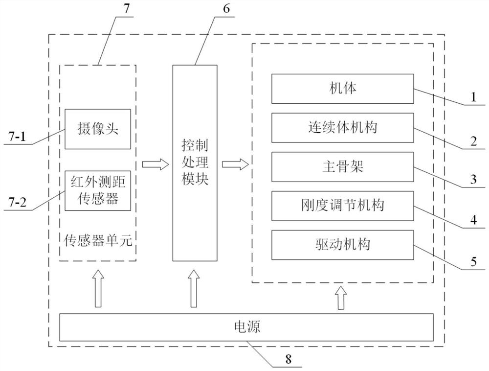
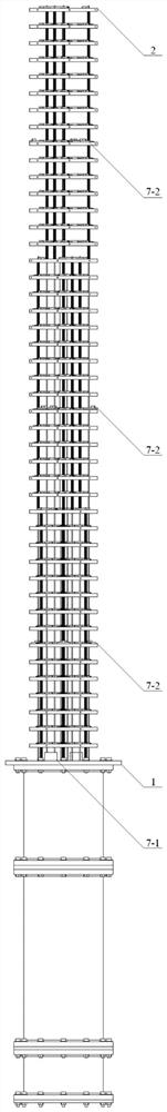
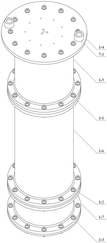
[0040] Example: refer to figure 1 , a continuum robot with bionic rigid-flexible coupling and variable stiffness is composed of a body 1, a continuum mechanism 2, a main skeleton 3, a stiffness adjustment mechanism 4, a drive mechanism 5, a control processing module 6, a sensor unit 7, and a power supply 8. The body 1 is used to install, fix and support the above-mentioned mechanisms, units and modules, the continuum mechanism 2 realizes the bending and winding function of the robot, the main skeleton 3 passes through the center of the continuum mechanism 2 as a skeleton, and the stiffness adjustment mechanism 4 realizes the rigidity of the robot Adjustment function, the driving mechanism 5 realizes the control of the continuum mechanism 2, the main frame 3 and the stiffness adjustment mechanism 4, the control processing module 6 realizes the driving of the driving mechanism 5, and the sensor data processing and storage of the sensor unit 7, and the sensor unit 7 realizes the r...
PUM
Abstract
The invention discloses a bionic rigid-flexible coupling variable-rigidity continuum robot and a control method, the continuum robot comprises a machine body, continuum mechanisms, a main framework, a rigidity adjusting mechanism, a driving mechanism, a sensor unit, a control processing module and a power module, and the continuum mechanisms comprise a first continuum mechanism, a second continuum mechanism and a third continuum mechanism; each rigid mechanism is composed of a plurality of circular rigid section pieces, an elastic rod and a compression spring, each rigidity adjusting mechanism is composed of a plurality of sets of friction sliding blocks, springs, pressing blocks, pull rods, connecting rods, connecting shafts, rotating discs, torsional springs and pull ropes, and the control method comprises a pose control method and a rigidity control method. The continuum robot has the advantages of being compact in structure, light, flexible, controllable in rigidity and the like, and winding and grabbing of objects can be achieved.
Description
technical field [0001] The invention belongs to the intersection field of robotics, control science, computer science and sensing technology, and is specifically a bionic rigid-flexible coupling variable stiffness continuum robot and a control method. Background technique [0002] Traditional industrial manipulators are composed of rigid links and discrete joints, simulating the human arm to achieve a given trajectory in a large working space so that the end of the manipulator reaches the designated working position. However, this type of rigid manipulator has less degrees of freedom and insufficient flexibility. In the face of complex working environments, inevitable rigid collisions will occur, posing safety hazards. The continuum robot is a new type of bionic robot. Different from the traditional manipulator arm, the bionic continuum robot imitates flexible biological organs such as elephant trunks and octopus tentacles. The main movement form of the bionic continuum rob...
Claims
Application Information
Patent Timeline
Application Date:The date an application was filed.
Publication Date:The date a patent or application was officially published.
First Publication Date:The earliest publication date of a patent with the same application number.
Issue Date:Publication date of the patent grant document.
PCT Entry Date:The Entry date of PCT National Phase.
Estimated Expiry Date:The statutory expiry date of a patent right according to the Patent Law, and it is the longest term of protection that the patent right can achieve without the termination of the patent right due to other reasons(Term extension factor has been taken into account ).
Invalid Date:Actual expiry date is based on effective date or publication date of legal transaction data of invalid patent.