High-speed low-nitrogen combustor for heating furnace and combustion method of high-speed low-nitrogen combustor

A low-nitrogen burner and heating furnace technology, which is applied in the direction of combustion methods, burners, gas fuel burners, etc., can solve the problems of high oxidized burning loss rate of steel billets, high nitrogen oxide emissions, and high carbon emissions, so as to reduce nitrogen Oxide, ensuring rigidity, and preventing tempering effects

Pending Publication Date: 2022-03-25
北京瑞晨航宇能源科技有限公司
View PDF10 Cites 0 Cited by
  • Summary
  • Abstract
  • Description
  • Claims
  • Application Information

AI Technical Summary

Problems solved by technology

[0004] A high-speed low-nitrogen burner is proposed to solve the problems of high energy consumption, high carbon emissions, high nitrogen oxide emissions, and high oxidation and burning rate of steel billets in the metallurgical conventional walking heating furnace process. By improving the core equipment of the walking heating furnace Burner technology development, by improving the core combustion equipment and system technology level, thereby improving the process level of the entire walking furnace, achieving a substantial reduction in carbon and nitrogen in the metallurgical iron and steel production process and improving product yield

Method used


Image

  • High-speed low-nitrogen combustor for heating furnace and combustion method of high-speed low-nitrogen combustor
  • High-speed low-nitrogen combustor for heating furnace and combustion method of high-speed low-nitrogen combustor
  • High-speed low-nitrogen combustor for heating furnace and combustion method of high-speed low-nitrogen combustor

Examples


Embodiment Construction

[0034] The specific embodiments of the present invention are described below so that those skilled in the art can understand the present invention, but it should be clear that the present invention is not limited to the scope of the specific embodiments. For those of ordinary skill in the art, as long as various changes Within the spirit and scope of the present invention defined and determined by the appended claims, these changes are obvious, and all inventions and creations using the concept of the present invention are included in the protection list.

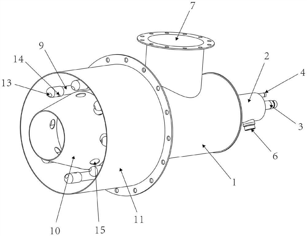
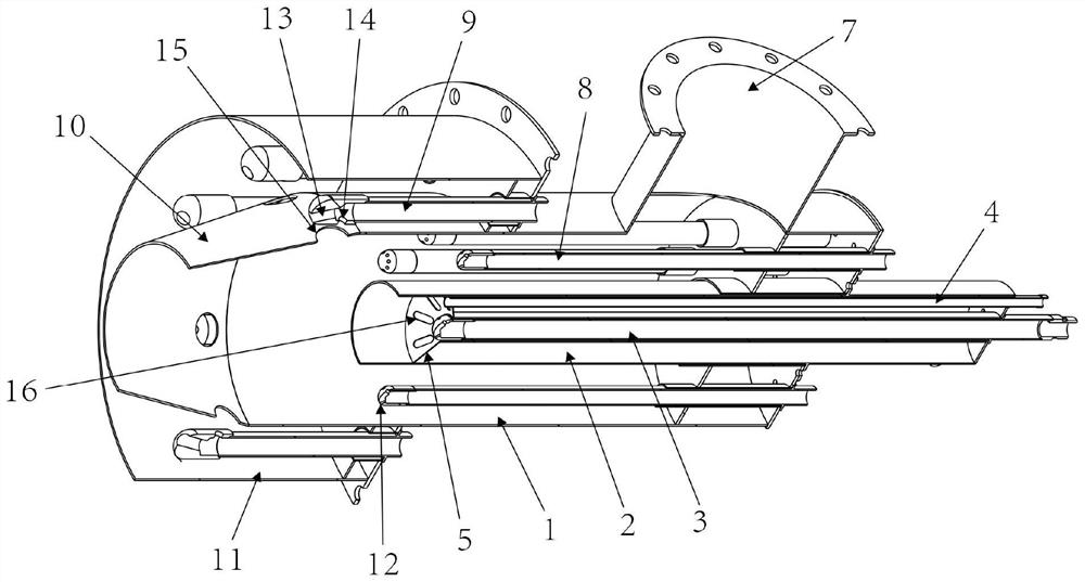
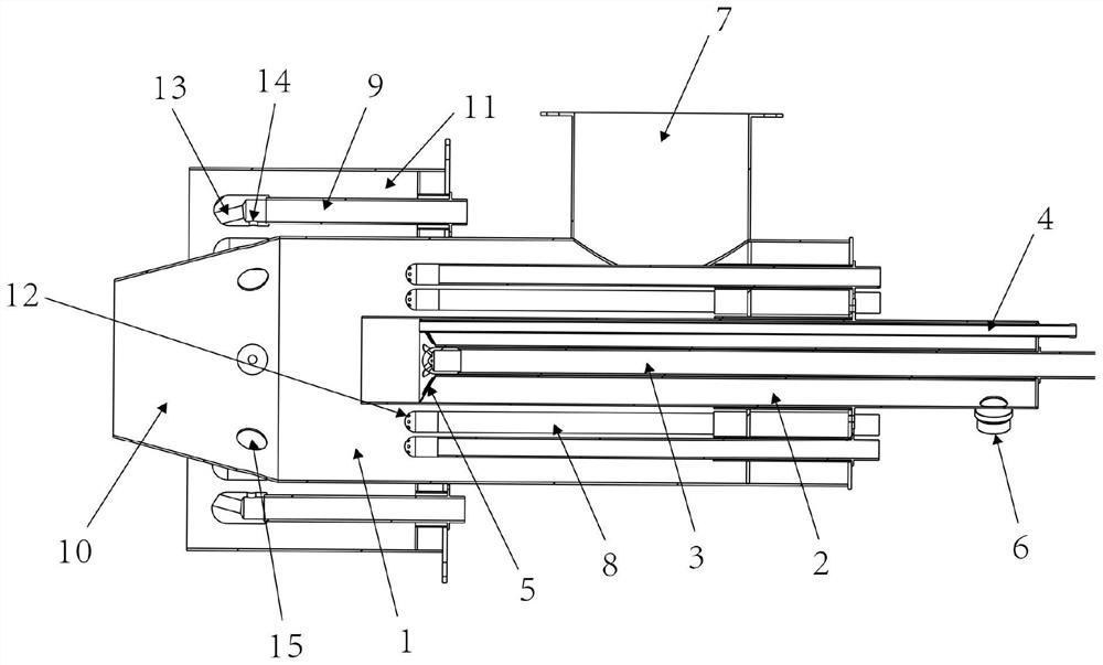
[0035] Such as figure 1 As shown, the high-speed low-nitrogen burner used in the heating furnace of this program includes a lower straight cylinder 1, a center gun 2 is arranged at the center of the interior of the lower straight cylinder 1, and a central fuel gun 3 and an ignition gun 4 are arranged inside the center gun 2 , and the center fuel gun 3 is arranged at the center of the center gun 2, the front ends of the cent...


PUM


Abstract

The high-speed low-nitrogen combustor comprises a lower straight barrel, a center gun is arranged in the lower straight barrel, a center fuel gun and an ignition gun are arranged in the center gun, the front end of the center fuel gun and the front end of the ignition gun are both arranged on a flame stabilizing device, and the flame stabilizing device is arranged at an opening in the front end of the center gun. A first air inlet is formed in the side face of the center gun, a second air inlet is formed in the side face of the lower straight barrel, a plurality of first fuel guns are arranged in the lower straight barrel and evenly and annularly distributed on the periphery of the center gun, and ports of the lower straight barrel, the center gun, the center fuel gun and the first fuel guns are located on the same side. According to the scheme, the nitrogen reduction strategy of staged combustion is adopted, combusted mixed gas is divided into three stages to be combusted in the axial direction, flames diverging from the center to the outer layer are formed, and therefore the combustor has the effects of reducing the oxidation burning loss rate, reducing generation of thermal nitrogen oxide and improving the steel billet yield.

Description

technical field [0001] The invention relates to the technical field of burners, in particular to a high-speed low-nitrogen burner for heating furnaces and a combustion method thereof. Background technique [0002] In the production process of the metallurgical industry, the hot rolling heating furnace is a large energy consumer. At present, there is still a lot of room for improvement in the fine control of the stepping heating furnace, which can improve the control accuracy of the heating furnace, reduce energy waste and product loss, and reduce carbon for the entire metallurgical industry. and nitrogen reduction are of great significance; the conventional walking heating furnace refers to the slab with basically the same shape, which moves continuously inside the heating furnace, from the entrance of the heating furnace to the exit under the drive of the roller, and the heating furnace The flame heating furnace steel slab produced by burning the burner arranged at a specif...

Claims


Application Information

Patent Timeline
IPC IPC(8): F23D14/08F23D14/64F23D14/46F23D14/82F23D14/58
CPCF23D14/08F23D14/64F23D14/46F23D14/82F23D14/58F23D2203/007
Inventor 邢玉明郝兆龙陈万东
Owner 北京瑞晨航宇能源科技有限公司
Why Eureka
Try Eureka