Motorized platform double-base foresight SAR trajectory design method

A dual-base forward-looking and trajectory design technology, applied in the radar field, can solve the problems of analysis methods and spatial resolution that cannot be directly used with GEO dual-base SAR, and achieve the effect of imaging performance optimization

Active Publication Date: 2022-03-25
UNIV OF ELECTRONICS SCI & TECH OF CHINA
View PDF10 Cites 1 Cited by
  • Summary
  • Abstract
  • Description
  • Claims
  • Application Information

AI Technical Summary

Problems solved by technology

Literature "Meng Ziqiang, Li Yachao, Wang Zongfu, Wu Chunfeng, Xing Mengdao, Bao Zheng. Ballistic Design Method for the Subduction Section of Missile-borne Bistatic Forward-Looking SAR[J]. Systems Engineering and Electronic Technology, 2015,37(04):768-774" A trajectory design method for missile-borne bistatic forward-looking SAR is proposed. However, this method only considers the trajectory design of the transmitter. At the same time, the analysis of imaging performance in this design method mainly considers the resolution in the range direction. Other indicators such as signal-to-noise ratio The included angle between the resolution and the resolution was not analyzed; the literature "Resolution calculation and analysis in bistatic SAR with geostationary illuminator," IEEE Geosci. The spatial resolution is analyzed in the case of a spherical surface and a large equivalent angle, but the analysis method and characteristics of the spatial resolution cannot be directly applied to the GEO bistatic SAR with non-zero inclination

Method used


Image

  • Motorized platform double-base foresight SAR trajectory design method
  • Motorized platform double-base foresight SAR trajectory design method
  • Motorized platform double-base foresight SAR trajectory design method

Examples


Embodiment Construction

[0090] The present invention will be further described in detail below in combination with specific embodiments.

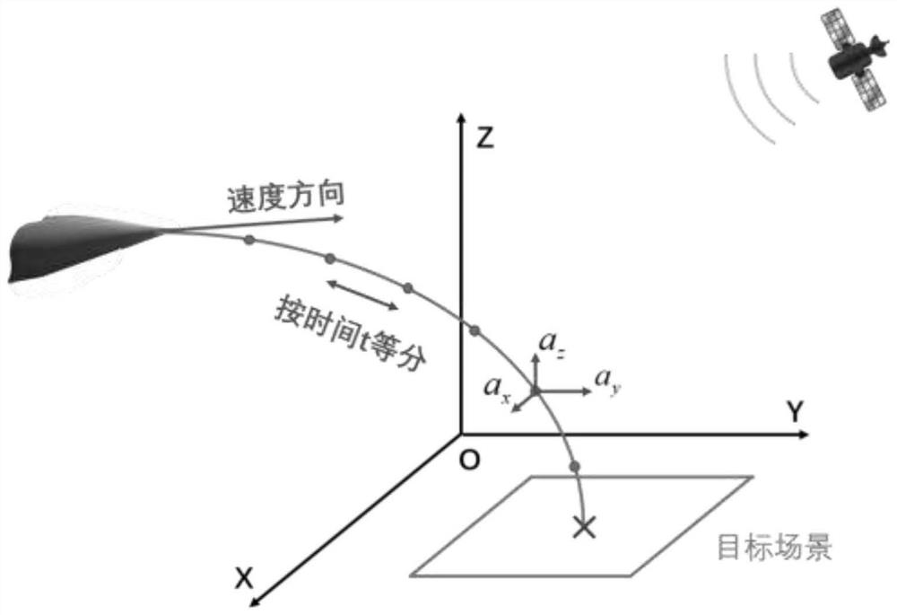
[0091] The geometric structure figure of the embodiment of the present invention is as figure 1 Shown, the GEO-SAR system parameter that the specific implementation mode adopts is as shown in table 1, and the satellite selects the geostationary orbit satellite of 30,000 6,000 kilometers away from the earth's surface, and in the present embodiment it is regarded as stationary relative to the target, The satellite incident angle is the angle between the star-eye line and the Z-axis)

[0092] Table 1

[0093]

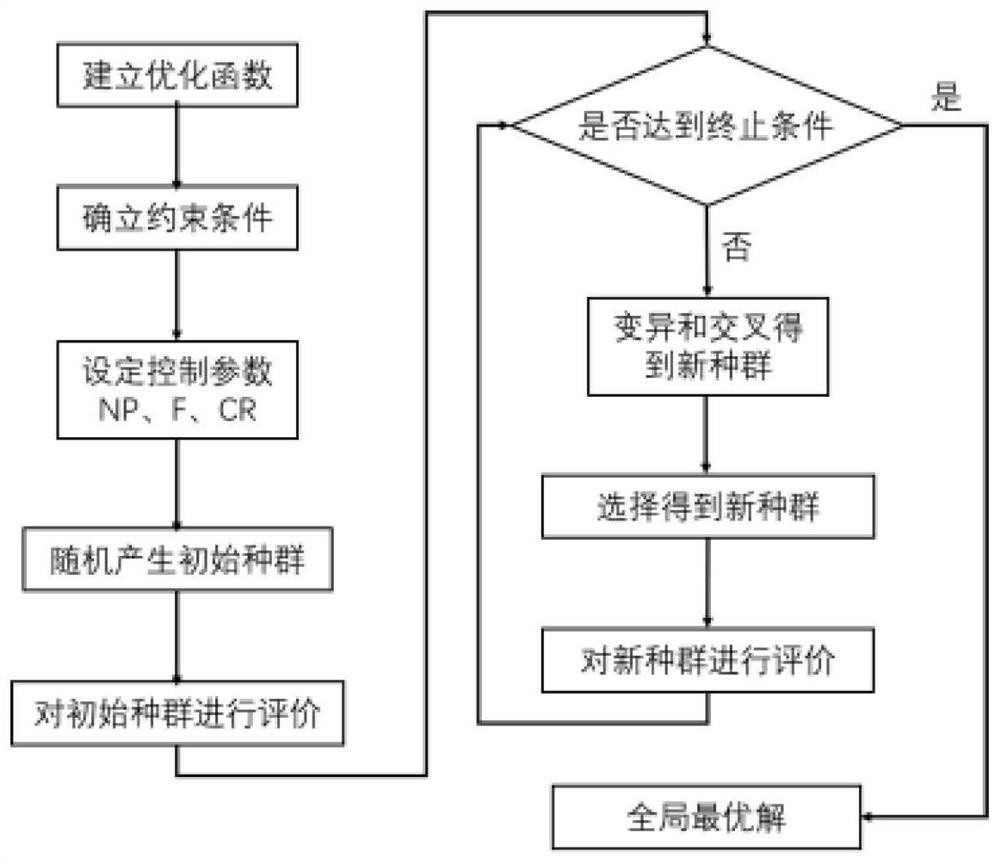
[0094] The specific process is as figure 2 shown, including the following steps:

[0095] Step S1: Divide the flight trajectory into N segments evenly by time, such as figure 2 As shown, the time of each period is t, and the acceleration of the high-speed motion platform is recorded as [a x ,a y ,a z ], representing the acceleration in the three di...


PUM


Abstract

The invention discloses a maneuvering platform double-base foresight SAR track design method, which utilizes GEO-SAR as an irradiation source and a high-speed maneuvering platform as a receiving station to realize foresight imaging, comprehensively considers the flight performance and the imaging performance of the platform, models the actual situation, determines a proper optimization function and a constraint condition, and achieves the target tracking of the high-speed maneuvering platform. According to the method, a trajectory design problem is modeled into a multi-constraint dual-objective optimization problem, then a state variable and a control variable are discretized, and the optimization problem is solved by adopting a multi-objective differential evolution algorithm, so that the dual-base forward-looking SAR trajectory design of the high-speed maneuvering platform is realized. A flight path which meets imaging indexes and can accurately reach a target landing point can be calculated, and forward-looking imaging performance optimization of the high-speed motion platform is achieved.

Description

technical field [0001] The invention belongs to the technical field of radar, and relates to a method for designing a bibase forward-looking SAR trajectory of a mobile platform based on GEO-SAR satellite irradiation. Background technique [0002] Synthetic Aperture Radar (SAR) is an all-weather, all-weather high-resolution imaging system. By transmitting a linear frequency modulation (LFM) signal with a large time and wide bandwidth, the distance direction of the echo signal is matched and filtered to obtain a pulse compression signal. In this way, high resolution in the range direction is obtained, and high resolution in the azimuth direction is achieved by using synthetic aperture technology. The imaging quality is not affected by weather conditions (clouds, light), etc., and it has the characteristics of detecting and locating long-distance targets. Typical applications of SAR include disaster monitoring, resource exploration, geological surveying and mapping, etc. [00...

Claims


Application Information

Patent Timeline
Patent Type & Authority Applications(China)
IPC IPC(8): G01S13/90
CPCG01S13/9043G01S13/9058
Inventor 孙稚超孙华瑞安洪阳陈天夫任航武俊杰杨建宇
Owner UNIV OF ELECTRONICS SCI & TECH OF CHINA
Why Eureka
Try Eureka