

Current feedback protection method and system for electron multiplier
An electron multiplier tube and current feedback technology, which is applied in the field of plasma diagnosis, can solve the problems of affecting the service life, the electron multiplier tube is easily damaged, and the anode current of the electron multiplier tube is too large, so as to reduce the anode current and improve the system reliability. Effect
- Summary
- Abstract
- Description
- Claims
- Application Information
AI Technical Summary
Problems solved by technology
Method used
Image

Examples
Embodiment 1
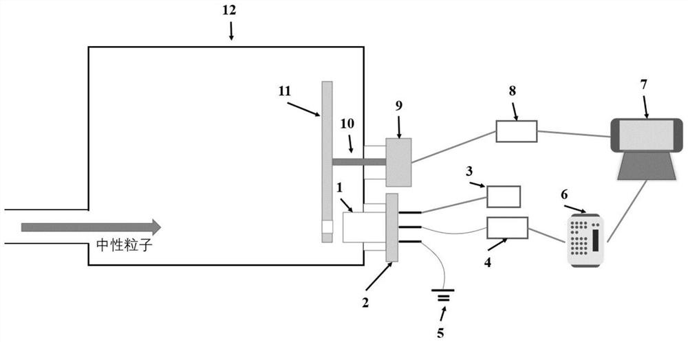
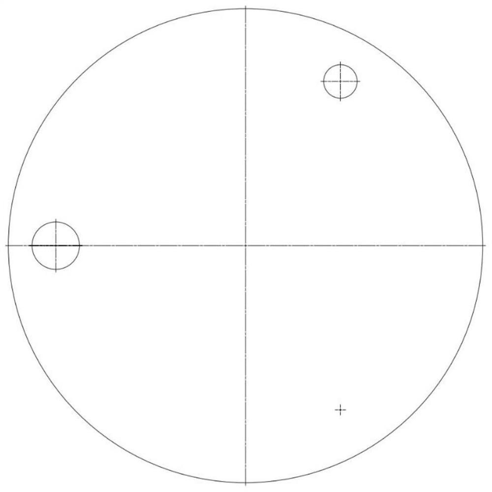
[0039] First of all, when the plasma discharge experiment is about to start, the PLC can be actively controlled by the computer 7 to generate a PLC control signal, so that the state of the control module becomes normal, that is, the area of the circular disc 11 with holes is S by rotating the motor 9. em The circular hole is located directly in front of the electron multiplier tube 1;
[0040] like figure 2 As shown, the high-voltage pole, signal pole, and ground pole of the electron multiplier tube are connected to the high-voltage power supply 3, the preamplifier 4, and the diagnostic ground terminal 5 respectively through the electrode flange 2;
[0041] After the plasma discharge experiment started, such as figure 2 As shown, the neutral particles enter the electron multiplier tube 1 after passing through the circular disc 11 with a hole, and are converted into secondary electrons. After the secondary electrons are multiplied, the anode current signal is formed, and f...
Embodiment 2
[0049] Based on the current feedback protection method in the specific implementation, this embodiment 2 provides a current feedback protection system for electron multiplier tubes, including:
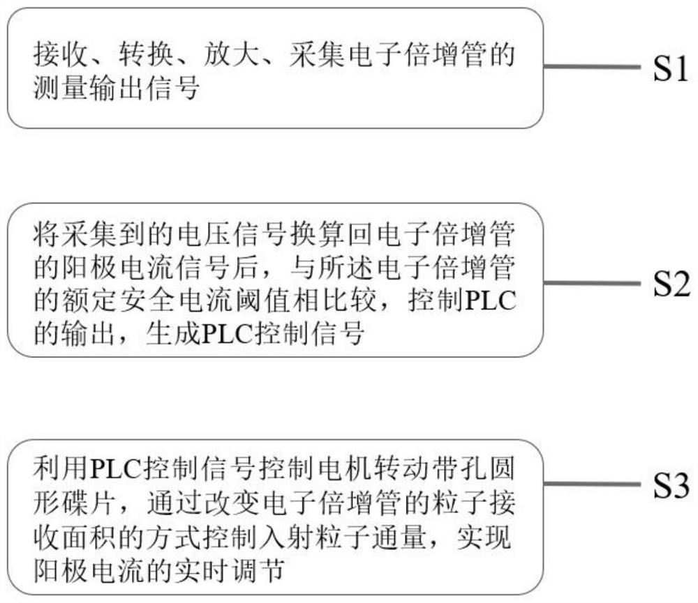
[0050] The sampling module is used for receiving, converting, amplifying and collecting the anode current signal;
[0051] The control module is used to compare the anode current signal of the electron multiplier tube 1 with the rated safety current threshold of the electron multiplier tube 1, control the output of the PLC8, and generate a PLC control signal. The computer 7 receives the voltage signal output by the data acquisition card 6, and divides it by the current conversion factor of the preamplifier 4, converts back to the anode current signal of the electron multiplier tube 1, and calculates the anode current signal and the rated safe current of the electron multiplier tube 1 The ratio of the threshold value is output to PLC8, and PLC8 generates a PLC control signal according t...
PUM
 Abstract
Description
Claims
Application Information