Brush carrier structure for alternator

A technology of alternators and brush holders, which is applied in the direction of electrical components, electromechanical devices, electric components, etc., can solve the problems of reducing the wear resistance of carbon brushes, affecting the conductivity of carbon brushes, and affecting carbon brushes, etc., to achieve airtightness and Good scalability, simple structure, and convenient assembly

Active Publication Date: 2022-03-25
成都华川电装有限责任公司
View PDF9 Cites 0 Cited by
  • Summary
  • Abstract
  • Description
  • Claims
  • Application Information

AI Technical Summary

Problems solved by technology

Because the carbon brush and the collector ring are in contact with each other, when the generator rotates at high speed to generate electricity, the carbon brush and the collector ring will rub against each other. If the brush is not wear-resistant, the carbon brush is easily worn to the point that it cannot contact the collector ring. As a result, the generator cannot continue to generate electricity, and the sealing of the brush holder directly affects whether the carbon brush is wear-resistant, so the sealing and powder discharge effect of the brush holder directly affect the life of the generator
[0003] The upper end of the existing brush holder is the brush holder body, and the lower end is provided with a protective cover fixed to the brush holder body. The brush holder body is provided with a vertically downward brush. Since there is a gap between the brush holder body and the protective cover, It is easy to cause foreign matter such as dust to enter the brush holder from the gap and adhere to the brush or collector ring, reducing the wear resistance of the carbon brush, and the water vapor generated by rainwater is easy to enter the brush holder from the gap, affecting the conductivity of the carbon brush sex

Method used


Image

  • Brush carrier structure for alternator
  • Brush carrier structure for alternator
  • Brush carrier structure for alternator

Examples


Embodiment Construction

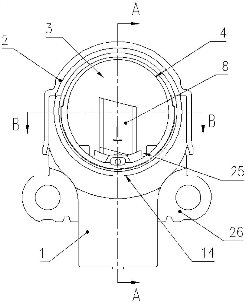
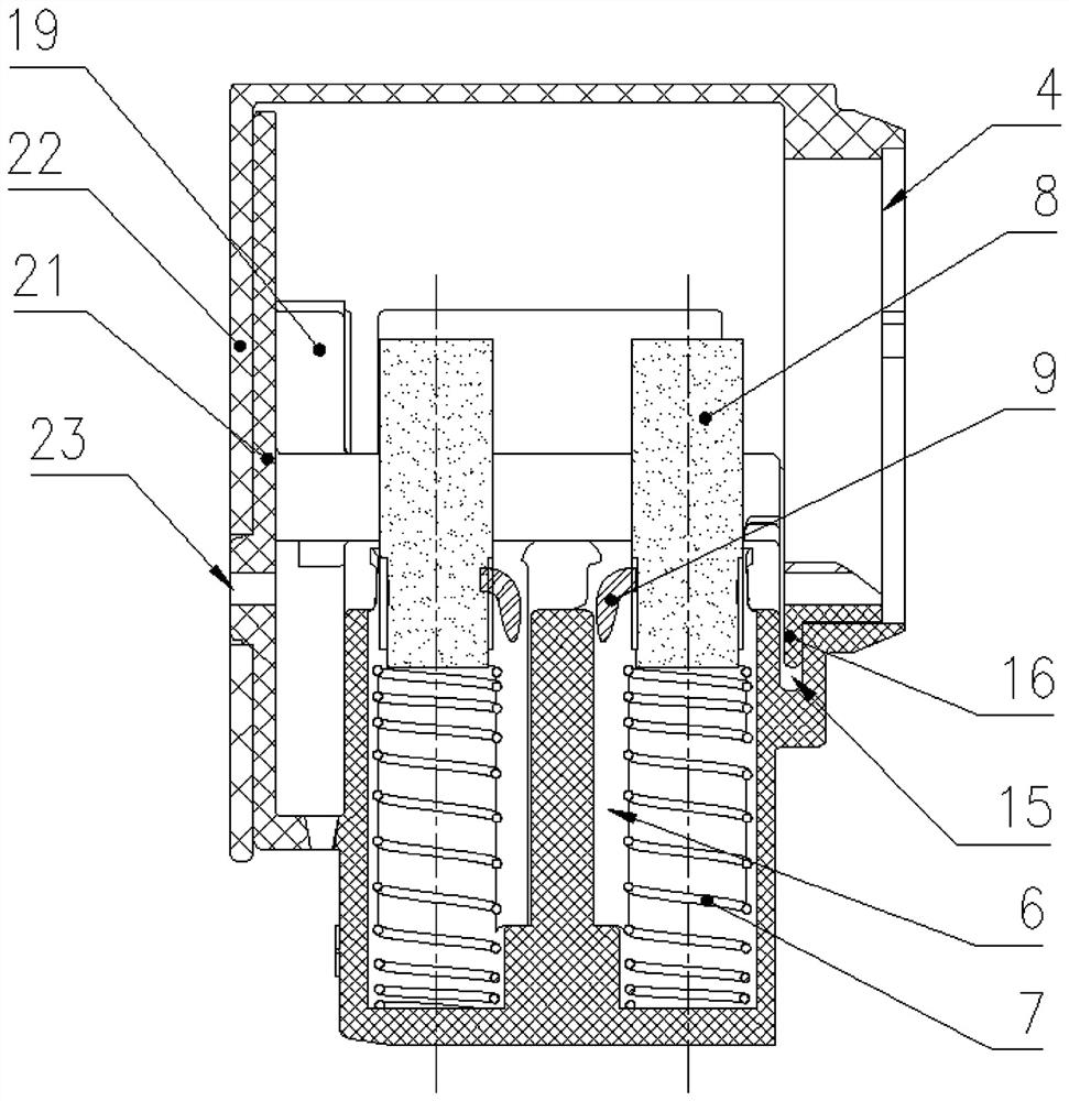
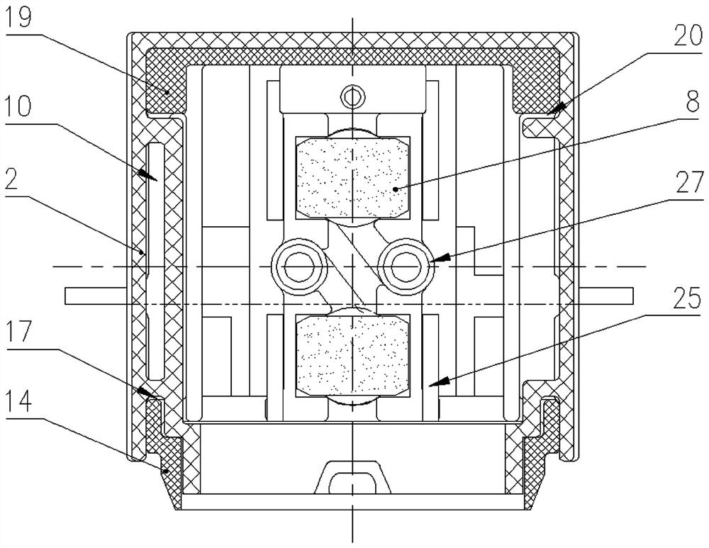
[0026] see Figure 1 to Figure 7 , a brush holder structure for an alternator, comprising a brush holder body 1 and a carbon brush protection cover 2. The upper end of the brush holder body 1 is provided with a cavity 3, the upper end and the front end of the cavity 3 are open, the carbon brush protection cover 2 is covered on the upper end of the brush holder body 1, and the front end of the carbon brush protection cover 2 is arranged The cylinder 4 corresponds to the opening of the front end of the concave cavity 3, and the cylinder 4 is used for inserting the slip ring of the alternator. The rear end of the brush holder body 1 is provided with a first baffle plate 21 extending upward, so that The rear end of the carbon brush protection cover 2 is provided with a second baffle plate 22 extending downward, and the carbon brush protection cover 2 is covered on the brush holder body 1, so that the first baffle plate 21 is located inside the second baffle plate 22, and the first...


PUM


Abstract

A brush holder structure used for an AC generator comprises a brush holder body and a carbon brush protection cover, the upper end of the brush holder body is provided with a concave cavity, the upper end and the front end of the concave cavity are open, the carbon brush protection cover covers the upper end of the brush holder body, and the front end of the carbon brush protection cover is provided with a cylinder corresponding to the opening in the front end of the concave cavity. The cylinder is used for allowing a collecting ring of the alternating current generator to be inserted, the left side and the right side of the carbon brush protection cover extend downwards respectively, openings are reserved between the carbon brush protection cover and the left side and the right side of the brush holder body respectively, an exhaust channel is formed between the carbon brush protection cover and the brush holder body, and two guide grooves vertically extending upwards are formed in the brush holder body. Each guide groove is respectively communicated with the concave cavity, a compression spring is respectively matched in each guide groove in a sliding manner, the upper end of each compression spring is respectively provided with a carbon brush, the two carbon brushes respectively extend into the concave cavity to correspond to the collector ring, and the carbon brushes are respectively provided with a brush braid.

Description

technical field [0001] The invention relates to the technical field of brush holders, in particular to a brush holder structure for an alternator. Background technique [0002] The brush holder refers to the device for installing the brush, which connects the rotating conductive device and the external power supply through the brush to form an electrical path. As far as the alternator is concerned, the brush plays the role of connecting the collector ring during the power generation process, pre-excites the rotor, and prepares for the generator to generate electricity. Effects matter. Because the carbon brush and the collector ring are in contact with each other, when the generator rotates at high speed to generate electricity, the carbon brush and the collector ring will rub against each other. If the brush is not wear-resistant, the carbon brush is easily worn to the point that it cannot contact the collector ring. As a result, the generator cannot continue to generate e...

Claims


Application Information

Patent Timeline
Patent Type & Authority Applications(China)
IPC IPC(8): H02K5/14H02K5/10
CPCH02K5/14H02K5/10
Inventor 杨兵陈鹏宇
Owner 成都华川电装有限责任公司
Why Eureka
Try Eureka