Energy-saving control circuit of engine-driven power generation and electric welding dual-purpose machine

An engine-driven, energy-saving control technology, applied in the control of generators, control of generators through magnetic field changes, control systems, etc., can solve problems such as high energy consumption, inability to reduce third harmonic damage, etc., to reduce noise and fuel consumption. Effect

Pending Publication Date: 2022-03-25
WENLING JENNFENG IND
View PDF1 Cites 0 Cited by
  • Summary
  • Abstract
  • Description
  • Claims
  • Application Information

AI Technical Summary

Problems solved by technology

[0003] As disclosed in the patent number CN201721174356.2, a power generation electric welding machine includes a gasoline engine, an electric welding generator and a permanent magnet generator. The gasoline engine drives the permanent magnet generator to generate electricity, and the permanent magnet generator is connected to the electric welding generator through a current controller. , the rotor of the electric welding generator is embedded with excitation winding, the stator is embedded with small current winding, high current winding, auxiliary power supply winding and excitation power supply winding, the excitation winding in the rotor i

Method used


Image

  • Energy-saving control circuit of engine-driven power generation and electric welding dual-purpose machine
  • Energy-saving control circuit of engine-driven power generation and electric welding dual-purpose machine
  • Energy-saving control circuit of engine-driven power generation and electric welding dual-purpose machine

Examples


Embodiment Construction

[0025] The following are specific embodiments of the present invention and in conjunction with the accompanying drawings, the technical solutions of the present invention are further described, but the present invention is not limited to these embodiments.

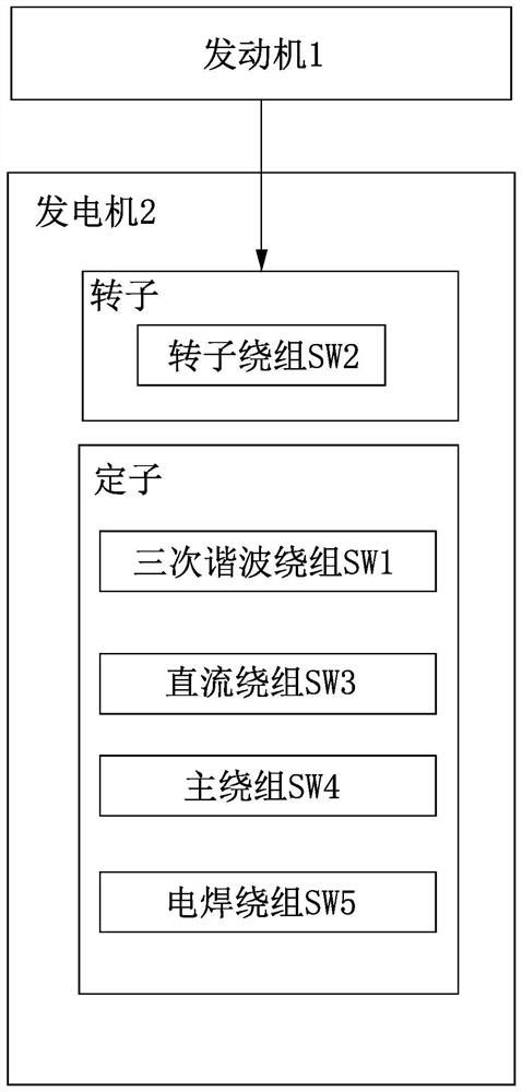
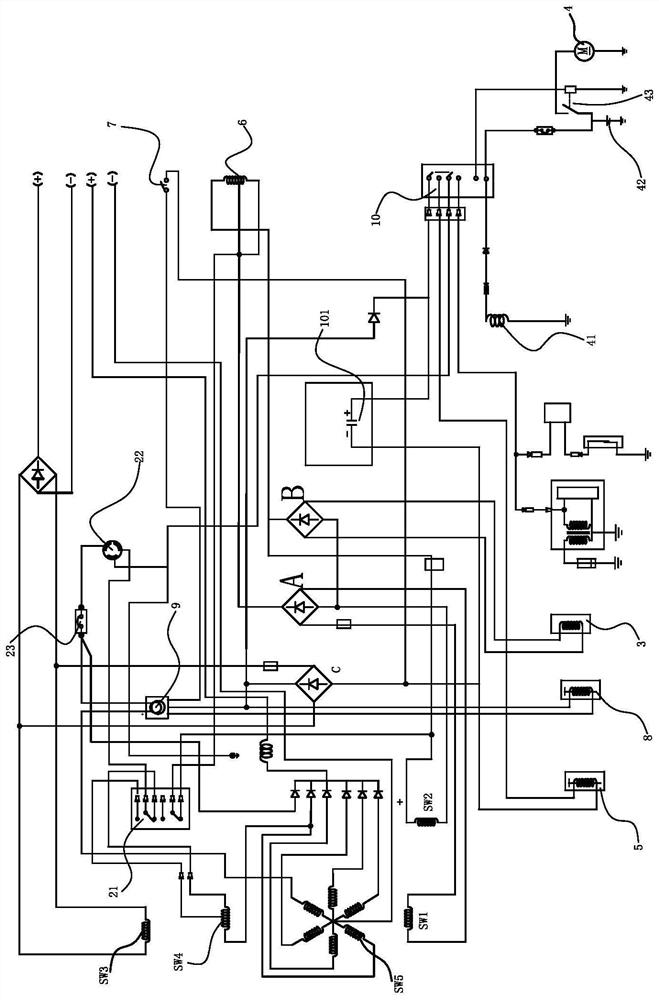
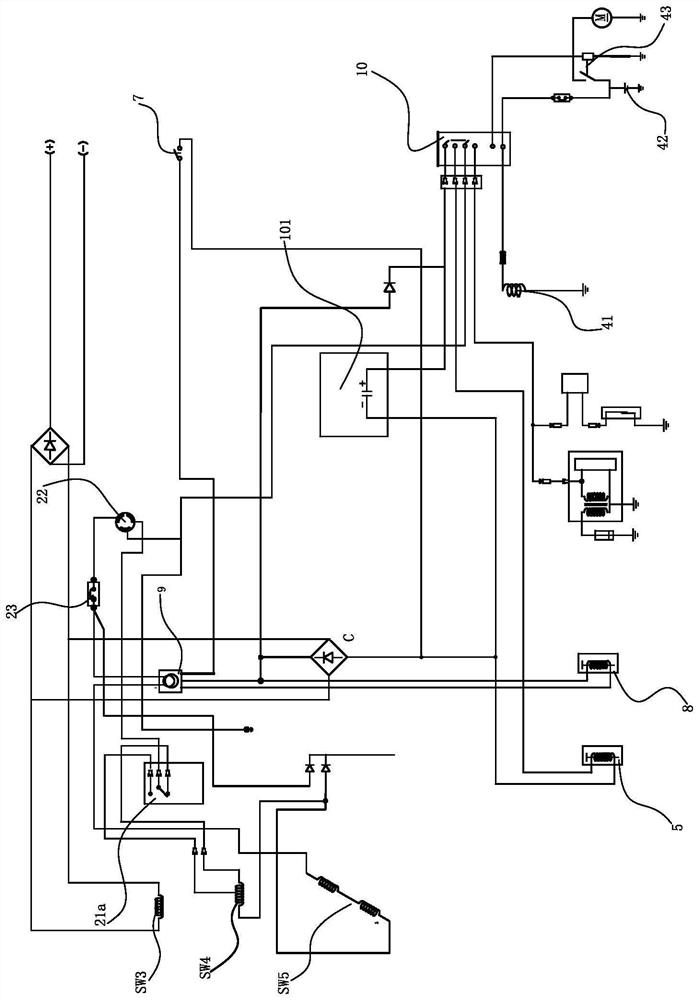
[0026] Such as figure 1 , figure 2 , image 3 , Figure 5 As shown, the energy-saving control circuit of the engine-driven electric welding dual-purpose machine includes a generator 2, an engine 1 for driving the generator 2 to generate electricity, and a magneto 3 connected to the engine 1. The generator 2 includes a The rotor winding SW2, the main winding SW4 set on the stator for outputting the generating current, the electric welding winding SW5 for outputting the welding current and the DC winding SW3 for power supply, the electric welding winding SW5 adopts a six-phase star connection, and the energy-saving control circuit also includes an idle speed The controller 9 and the control switch 21 for switching betwee...


PUM


Abstract

The invention provides an energy-saving control circuit of an engine-driven power generation and electric welding dual-purpose machine, which comprises an engine, a generator, a magnetor, a potentiometer, an idle speed controller and a control switch, and is characterized in that the generator comprises a third harmonic winding, a rotor winding, a direct current winding, a main winding and an electric welding winding, and the magnetor is connected with the rotor winding through a magnetor rectifying circuit; during welding, the potentiometer is connected between the harmonic rectification circuit and the rotor winding in series, and the main winding and the electric welding winding are connected in series and penetrate through the idle speed controller to be connected with the panel socket. The idle speed controller is connected with an energy-saving electromagnetic valve, the direct-current winding is connected with a direct-current rectifying circuit, the direct-current rectifying circuit is connected with the idle speed controller to supply power, the direct-current rectifying circuit is connected with a fuel oil stop valve through an electric door lock switch, and an electrolytic capacitor is connected to the direct-current rectifying circuit in parallel. The control circuit can achieve an energy-saving effect.

Description

technical field [0001] The invention relates to the technical field of DC electric welding machines, in particular to an engine-driven power generation and electric welding dual-purpose machine, and in particular to an energy-saving control circuit of the DC electric welding machine. Background technique [0002] At present, similar power generation and welding dual-purpose machines on the market mainly include engines and generators, and the conventional excitation methods of synchronous generators: one is to use brushless excitation, but the voltage stabilization performance of brushless excitation is poor, especially with inductive and capacitive The load performance is poor; the second is to use brush excitation, but it needs a voltage regulator (AVR). In a pole synchronous generator, when the rotor coil of the main engine is fed with direct current, an approximately rectangular magnetomotive force wave is generated on the magnetic pole. Due to the uneven air gap between...

Claims


Application Information

Patent Timeline
IPC IPC(8): H02P9/00H02P9/38H02P9/04H02P9/14B23K37/00H02P101/25
CPCH02P9/00H02P9/38H02P9/04H02P9/14B23K37/00H02P2101/25
Inventor 许式省张长义徐明
Owner WENLING JENNFENG IND
Why Eureka
Try Eureka