Laser welding method based on automatic alignment device and device

A laser welding and automatic alignment technology, applied in laser welding equipment, auxiliary devices, welding equipment, etc., can solve the problems of affecting the welding strength of the steel bottom and the cup body, polluting the cup body, and the offset of the steel bottom, so as to improve the finished product. The effect of quality, ease of positioning, and reduced difficulty of cleaning

Pending Publication Date: 2022-03-29
浙江安胜科技股份有限公司
View PDF0 Cites 0 Cited by
  • Summary
  • Abstract
  • Description
  • Claims
  • Application Information

AI Technical Summary

Problems solved by technology

[0006] In view of the above-mentioned shortcomings existing in the prior art, the present invention provides a laser welding method based on an automatic alignment device and the device, which can effectively solve the problem of lack of corrective adjustment of the welding position between the steel bottom and the cup body in the prior art during the welding process. For temperature monitoring measures, if the temperature is too high or too low due to a fault, it will greatly affect the welding strength between the steel bottom and the cup body, and in the process of aligning the cup body and the steel bottom, relying on the suction force of the magnet, The stability will be poor, the steel bottom is easy to shift during the transmission process, and the magnet will also pollute the inside of the cup body

Method used


Image

  • Laser welding method based on automatic alignment device and device
  • Laser welding method based on automatic alignment device and device
  • Laser welding method based on automatic alignment device and device

Examples


Embodiment 1

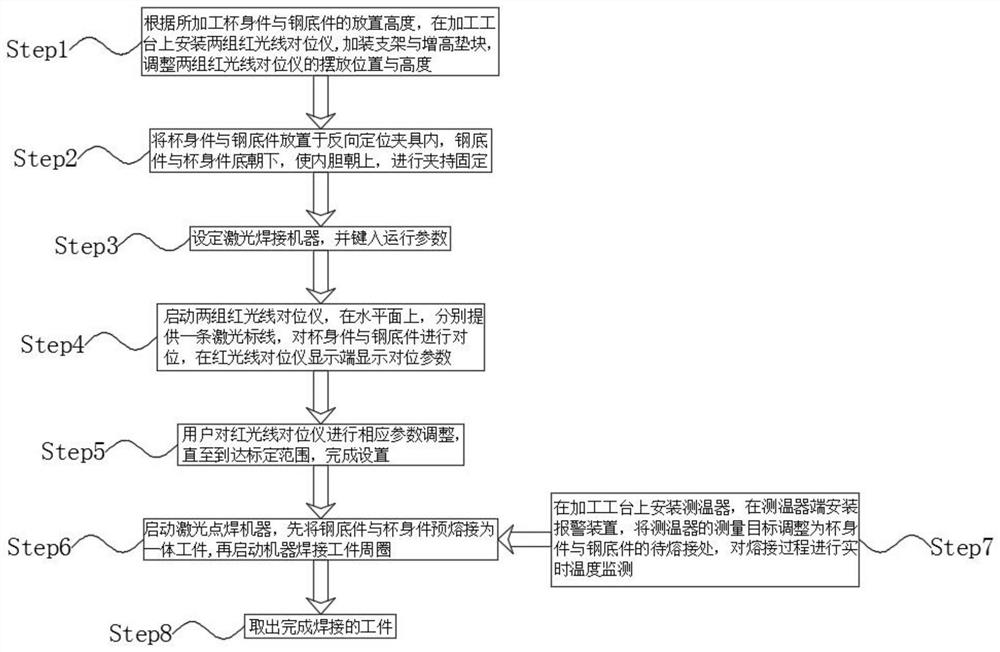
[0052] The laser welding method based on the automatic alignment device of the present embodiment, such as figure 1 shown, including the following steps:

[0053] Step1: According to the height of the processed cup body and steel bottom, install two sets of red light alignment instruments on the processing table, install brackets and heightening pads, and adjust the placement positions of the two sets of red light alignment instruments and height;

[0054] Step2: Place the cup body and steel bottom part in the reverse positioning fixture, the steel bottom part and the cup body face down, make the inner liner face up, and clamp and fix, the steel bottom part and the cup body surface Logo keep consistent;

[0055] Step3: Set up the laser welding machine and enter the operating parameters;

[0056] Step4: Start two sets of red light alignment instruments, provide a laser marking line on the horizontal plane, align the cup body and steel bottom, and display the alignment parame...

Embodiment 2

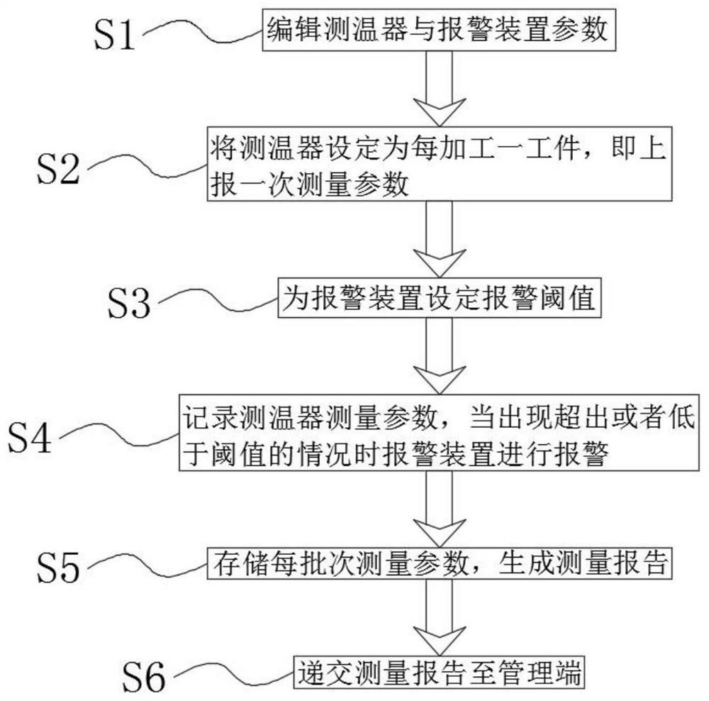
[0074] At other levels, such as figure 2 As shown, the setting method of real-time temperature monitoring in the step Step7 includes the following steps:

[0075] S1: Edit the parameters of the temperature detector and alarm device;

[0076] S2: Set the temperature detector to report the measurement parameters once every time a workpiece is processed, and measure the temperature during welding;

[0077] S3: setting an alarm threshold for the alarm device;

[0078] S4: Record the measurement parameters of the temperature detector, and the alarm device will alarm when the situation exceeds or falls below the threshold;

[0079] S5: Store each batch of measurement parameters and generate a measurement report;

[0080] S6: Submit the measurement report to the management terminal.

[0081] Such as figure 2 As shown, the temperature detector and the alarm device are interactively connected through a wireless network, and the temperature detector shares data to the data receiv...

Embodiment 3

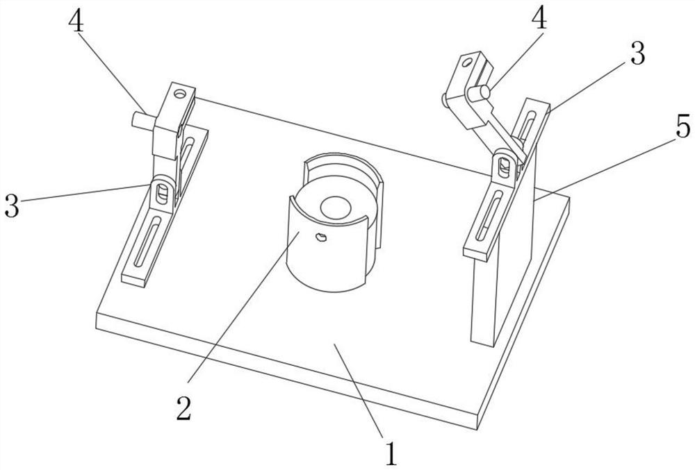
[0085] In this embodiment, an automatic alignment device, such as image 3 As shown, including a workbench 1, a reverse fixture 2 is installed in the middle of the top of the workbench 1, and two groups of infrared alignment instruments 4 are arranged on the top of the workbench 1, and the bottom of the infrared alignment instrument 4 A mounting frame 3 is installed at the end, and the mounting frame 3 is installed on the surface of the workbench 1, and the bottom end of the infrared alignment instrument 4 on the right side is provided with a cushion block 5.

[0086] In the actual implementation of this example, before welding the steel bottom part and the cup body, the user puts the cup body and the steel bottom part into the reverse clamp 2, adjusts the logo on the surface of the steel bottom part and the cup body to be consistent, and then Clamp it so that both the steel bottom part and the cup body face down, and the liner faces up without touching any objects, which effe...


PUM


Abstract

The invention relates to the field of laser welding, and discloses a laser welding method and device based on an automatic alignment device.The laser welding method comprises the following steps that firstly, according to the placing height of a cup body part and a steel bottom part to be machined, two sets of red ray alignment instruments are installed on a machining workbench, a support and a heightening cushion block are additionally installed, and the cup body part and the steel bottom part are machined; adjusting the placement positions and heights of the two groups of red ray alignment instruments; 2, the cup body piece and the steel bottom piece are placed in a reverse positioning clamp, the bottoms of the steel bottom piece and the cup body piece face downwards, the inner container is made to face upwards, clamping and fixing are conducted, and the surface Logo of the steel bottom piece and the surface Logo of the cup body piece are kept consistent; and 3, a laser welding machine is set, and operation parameters are input. In the welding process of the cup bottom and the cup body, the measure of monitoring the temperature of the welding position is added, the situation that due to faults of a laser machine, the welding temperature is too high or too low, the welding strength of the steel bottom and the cup body is affected is avoided, the quality of a finished product is improved, and the measure of conveniently conducting alignment fixing on the cup body and the steel bottom is added; and the connection stability is better.

Description

technical field [0001] The invention relates to the technical field of laser welding, in particular to a laser welding method based on an automatic alignment device and the device. Background technique [0002] Laser welding is an efficient and precise welding method that uses a high-energy-density laser beam as a heat source. Laser welding is one of the important aspects of the application of laser material processing technology. As a new welding technology, laser welding has high energy density and high speed. , high precision, deep penetration, strong adaptability and other characteristics, its application range is more and more extensive, the welding process is a heat conduction type, that is, the laser radiation heats the surface of the workpiece, and the surface heat diffuses to the interior through heat conduction, by controlling the width of the laser pulse, Parameters such as energy, peak power and repetition frequency, melt the workpiece and form a specific molten ...

Claims


Application Information

Patent Timeline
Patent Type & Authority Applications(China)
IPC IPC(8): B23K26/21B23K26/70B23K37/04
CPCB23K26/21B23K26/702B23K37/0443
Inventor 刘力吴永胜吴小龙
Owner 浙江安胜科技股份有限公司
Why Eureka
Try Eureka