
Aircraft fuel tank with energy absorption protection function and leading edge slat

A leading-edge slat and aircraft fuel tank technology, which is applied to power plant fuel tanks, layered products, chemical instruments and methods, etc., can solve problems such as occupying a large space, reducing the fuel storage capacity of the fuel tank, and weak buffering and energy-absorbing capabilities , to achieve the effect of preventing fuel leakage incidents, reducing the possibility and improving the anti-collision ability

Pending Publication Date: 2022-03-29
CIVIL AVIATION UNIV OF CHINA
View PDF9 Cites 0 Cited by
  • Summary
  • Abstract
  • Description
  • Claims
  • Application Information

AI Technical Summary

Problems solved by technology

[0003] At present, the protective structure of the front edge of the aircraft and the fuel tank is simple, and the impact resistance of the materials used is weak, it is difficult to resist the impact of foreign objects, and it is easy to be impacted and cause damage to internal components or damage to the fuel tank, which may cause the aircraft to fail to operate normally or the fuel tank to leak Oil poses a serious safety hazard
At present, the anti-collision ability of the bird strike structure of the leading edge structure is mainly improved by increasing the thickness of the skin and adding auxiliary beams in the leading edge, etc., but there are still insufficient strength, unable to meet the energy absorption requirements, and the structure is too complicated difficult to create problems
[0004] The Chinese invention patent with publication number CN109927918A discloses an aluminum alloy military aircraft fuel tank. Damping springs are connected to both sides of the fuel tank body to improve the impact resistance of the fuel tank. However, when the bottom of the fuel tank is hit, the fuel tank cannot be damaged. protection, there may be oil tank damage and oil leakage
The Chinese invention patent with the publication number CN109018386A discloses an anti-collision mechanism for an aircraft fuel tank. An anti-collision structure is set in the auxiliary fuel tank of the aircraft, but the structure is complex and occupies a large space, which greatly reduces the fuel storage capacity of the fuel tank.
The Chinese invention patent with the publication number CN10708212A discloses an anti-bird auxiliary fuel tank. A buffer layer is set inside the external auxiliary fuel tank to resist the impact force caused by the impact of birds. To resist the damage caused by the high-speed impact of the bird body, it cannot effectively protect the safety of the fuel tank
The Chinese invention patent with the publication number CN109229339A discloses an anti-bird strike structure at the leading edge of an aircraft, which absorbs the energy generated during the impact by installing a thin-walled tube filled with energy-absorbing material laterally, but the energy-absorbing stroke of the filling structure installed in this way Short, low energy absorption, unable to effectively resist bird impact

Method used


Image

  • Aircraft fuel tank with energy absorption protection function and leading edge slat
  • Aircraft fuel tank with energy absorption protection function and leading edge slat
  • Aircraft fuel tank with energy absorption protection function and leading edge slat

Examples


Embodiment 1

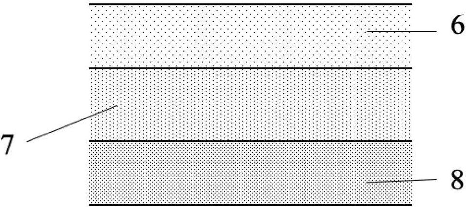
[0033] An aircraft fuel tank and leading-edge slats with energy-absorbing protection functions, such as figure 1 As shown, it includes a fuel tank 1 , a slat 2 and a rail chamber 3 , the fuel tank 1 and the slat 2 are connected through a guide rail 10 in the rail chamber 3 , and the guide rail 10 is assisted by a roller 11 . A buffer energy-absorbing layer 4 is arranged on the inner wall of the oil tank 1, and the buffer energy-absorbing layer 4 is a composite foam with a composition gradient. The composite foam with a composition gradient is made by powder metallurgy filling with a pore-forming agent. figure 2As shown, the buffer energy-absorbing layer 4 in this embodiment is composed of a pure aluminum foam layer 6, a middle carbon nanotube-reinforced aluminum-based composite foam layer 7, and an inner carbon nanotube-reinforced aluminum-based composite foam layer 8, which are sequentially arranged from outside to inside. The anti-bird strike structure in the leading edge s...

Embodiment 2

[0039] In this embodiment, the anti-bird strike structure includes a composite material layer and a gradient aluminum foam filling tube. The composite material layer is made by powder metallurgy filling and adding a pore-forming agent. Carbon nanotube reinforced aluminum matrix composite foam, the density of pure foamed aluminum is 0.54g / cm 3 , the corresponding porosity is 80%; the mass fraction of carbon nanotubes in the middle carbon nanotube reinforced aluminum matrix composite foam is 2wt.%, and the porosity is 70%; the mass fraction of carbon nanotubes in the inner carbon nanotube reinforced aluminum matrix composite foam is 2wt.%, the porosity is 60%. The gradient aluminum foam filling tube is made of 5 layers of density gradient aluminum foam with a porosity of 50-80% in situ filling an aluminum alloy thin-walled tube with a wall thickness of 2mm. The density gradually increases from the outside to the direction close to the fuel tank. The diameter of the foam aluminum...

Embodiment 3

[0042] In this embodiment, the anti-bird strike structure includes a composite material layer and a gradient aluminum foam filling tube. The composite material layer is made by powder metallurgy filling and pore-forming agent method. It consists of two layers of pure foam aluminum blocks on the outside and two layers of carbon nanotube reinforced aluminum in the middle. Al-based composite foam and two layers of carbon nanotube-reinforced aluminum-based composite foam on the inner side; along the direction close to the fuel tank, the density of the two outer layers of aluminum foam is 0.54g / cm 3 , 0.81g / cm 3 , the corresponding porosity is 80% and 70%, the mass fraction of carbon nanotubes in the middle two layers of carbon nanotube reinforced aluminum matrix composite foam is 2wt.%, the porosity is 70%, 60% respectively, the inner two layers of carbon nanotubes The mass fraction of carbon nanotubes in reinforced aluminum matrix composite foam is 2 wt.%, and the porosity is 60%...


PUM

PropertyMeasurementUnit
densityaaaaaaaaaa
diameteraaaaaaaaaa
thicknessaaaaaaaaaa

Abstract

The invention relates to the field of aircraft structure design, in particular to an aircraft fuel tank with an energy absorption protection function and a leading edge slat. A buffer energy absorption layer is arranged on the inner wall of the oil tank and comprises a pure foam aluminum layer, a middle carbon nano tube reinforced aluminum-based composite foam layer and an inner carbon nano tube reinforced aluminum-based composite foam layer which are sequentially arranged from outside to inside. A bird impact prevention structure is arranged on the leading edge slat, and the bird impact prevention structure comprises a composite material layer and a gradient foamed aluminum filling pipe; the composite material layer comprises a pure foam aluminum layer, a middle carbon nano tube reinforced aluminum-based composite foam layer and an inner side carbon nano tube reinforced aluminum-based composite foam layer which are sequentially arranged in the direction close to the oil tank. The multiple gradient foamed aluminum filling pipes are arranged in the composite material layer in a penetrating mode in the stacking direction perpendicular to the composite material layer. By utilizing the characteristics of the composition gradient composite foam and the gradient foamed aluminum filling pipe, the impact resistance is provided for the aircraft fuel tank and the leading edge slat, the possibility of fuel tank damage caused by impact of foreign objects is reduced, and the aircraft safety is improved.

Description

technical field [0001] The invention relates to the field of aircraft structure design, in particular to an aircraft fuel tank and leading-edge slats with energy-absorbing protection functions. Background technique [0002] With the development of science and technology and the improvement of people's living standards, the aviation field has developed rapidly, and aviation safety issues have also been continuously concerned. If the fuel tank that stores fuel leaks, it may cause the fuel tank to catch fire, resulting in a fire and endangering flight safety. Bird strikes are one of the important factors that threaten aviation safety. In China, the incidents caused by bird strikes have accounted for 1 / 3 of the total number of incidents. When a bird strikes the leading edge of the wing, it may cause damage to the fuel tank, and then fuel leakage will occur, threatening flight safety. In addition, there was an incident where a bolt pierced a fuel tank at the leading edge slat r...

Claims


Application Information

Patent Timeline
Patent Type & Authority Applications(China)
IPC IPC(8): B32B15/20B32B15/04B32B3/08B64D37/04B64D37/06
CPCB32B5/18B32B5/32B32B3/08B64D37/04B64D37/06B32B2262/106B32B2266/045Y02T50/40
Inventor 杨旭东冯晓琳林森邹田春
Owner CIVIL AVIATION UNIV OF CHINA
Learn More