Welding system for solder paste packaging of electronic connector

A technology of electronic connectors and welding systems, which is applied in the direction of assembling printed circuits, connections, circuit/collector components, etc. of electrical components, which can solve problems such as hidden dangers of solder paste heating, achieve stable control, and realize the effect of automatic control

Pending Publication Date: 2022-03-29
SHENZHEN HANGLIANTONG CONNECTOR TECH CO LTD
View PDF0 Cites 0 Cited by
  • Summary
  • Abstract
  • Description
  • Claims
  • Application Information

AI Technical Summary

Problems solved by technology

[0002] The electronic connector welding work in the prior art involves solder paste packaging and heating and drying work, printing and coating solder paste on the pads of the printed circuit board, and accurately attaching surface mount components to the solder coated On the pad of the paste, heat the circuit board according to a specific reflow temperature curve to melt the solder paste. After the alloy components are cooled and solidified, a solder joint is formed between the component and the printed circuit board. The solder paste is made of solder powder, auxiliary Solder paste is a paste mixed with flux and other additives. Solder paste has a certain viscosity at room temperature and can initially stick electronic components to a predetermined position. At the soldering temperature, with the volatilization of solvents and some additives, it will be Soldering components and printed circuit pads are welded together to form a permanent connection. In the use of traditional paste guns and heat guns, the paste guns and heat guns can be fixed and controlled by the machine tool to be placed side by side, which is convenient for tinning. The paste work and the heating and drying work are quickly connected, or the hot air gun outlet port is provided on the side of the paste gun, but because the distance between the paste injection port and the hot air port is too close, there is a hot air gun that is not discharged from the paste gun. Paste heating hazards, for this reason we provide a soldering system for solder paste packaging of electronic connectors, by separating the paste gun, heat gun and connector pick-and-place mechanism, so as to ensure that multiple working mechanisms do not affect each other , the entire process is automatically controlled, which effectively improves the packaging efficiency and safety of electronic connectors

Method used


Image

  • Welding system for solder paste packaging of electronic connector
  • Welding system for solder paste packaging of electronic connector
  • Welding system for solder paste packaging of electronic connector

Examples


Embodiment Construction

[0027] The following will clearly and completely describe the technical solutions in the embodiments of the present invention with reference to the accompanying drawings in the embodiments of the present invention. Obviously, the described embodiments are only some, not all, embodiments of the present invention. Based on the technical solutions in the present invention, all other embodiments obtained by persons of ordinary skill in the art without making creative efforts belong to the protection scope of the present invention.

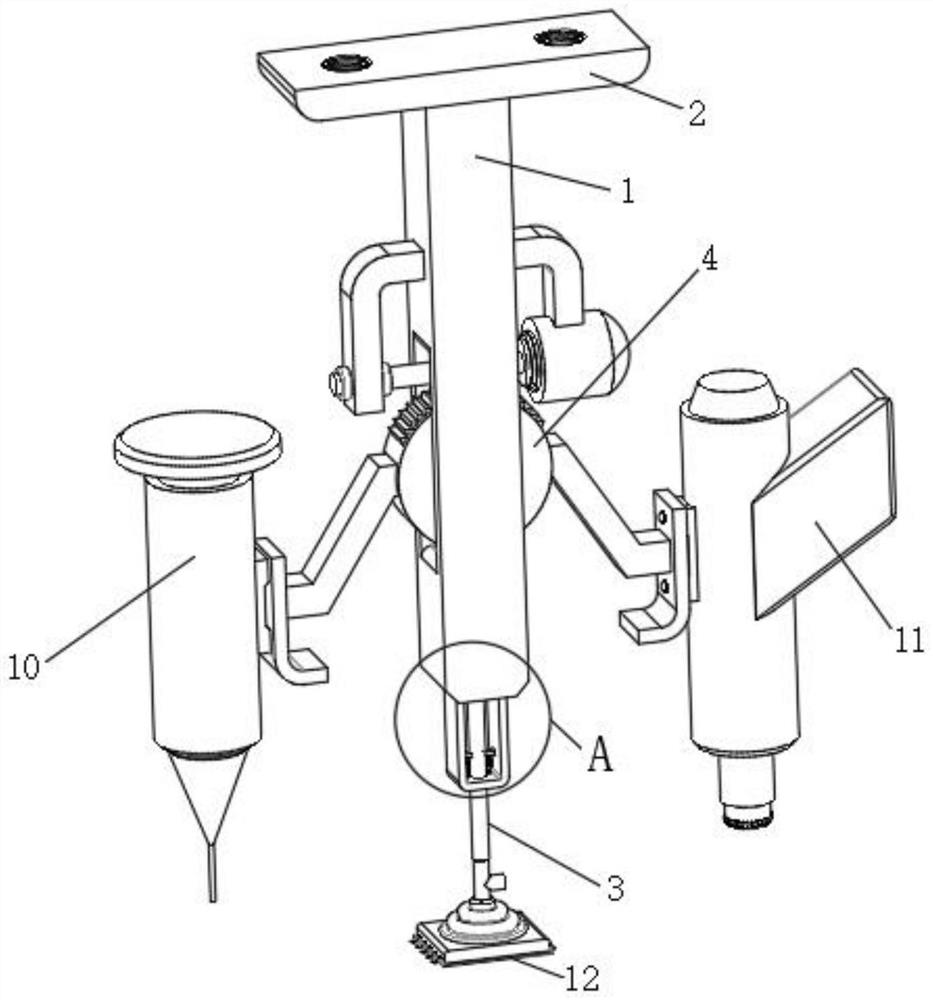
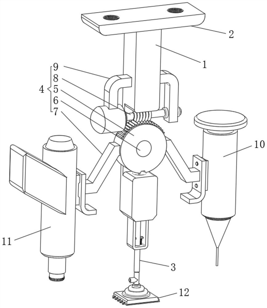
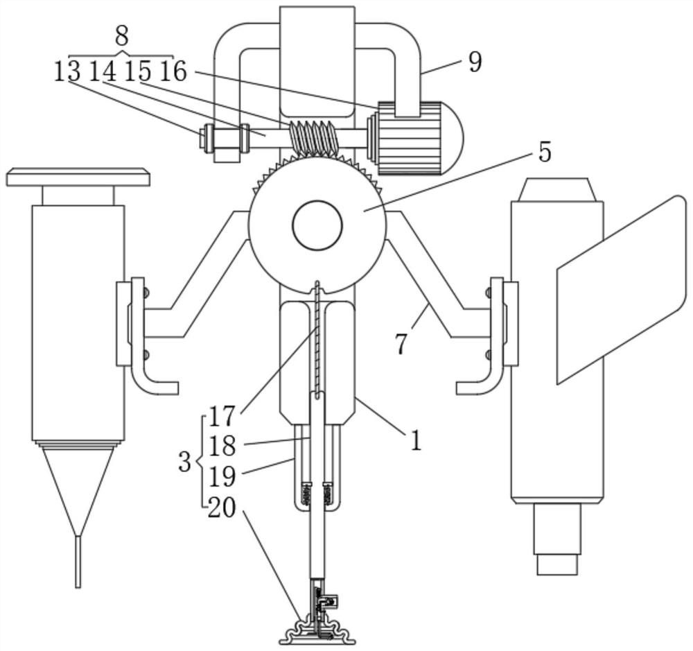
[0028] see Figure 1 to Figure 10 , the present invention provides a technical solution: a welding system for solder paste packaging of electronic connectors, including a central column 1, a top plate 2 is fixed on the top of the central column 1, and a control lifting frame 3 is connected to the bottom end of the central column 1 A square hole is opened in the middle of the center column 1, and a swing assembly 4 is arranged in the square hole. The sw...


PUM


Abstract

The invention relates to the technical field of solder paste welding, in particular to a welding system for solder paste packaging of an electronic connector, which comprises a middle column, a top plate is fixed at the top end of the middle column, a control lifting frame is connected to the bottom end of the middle column, a square hole is formed in the middle of the middle column, and a swing assembly is arranged in the square hole. The swing assembly comprises a control cylinder, a center shaft, supporting frames, a brake device and an outer plate frame, the center shaft is movably sleeved with the middle of the control cylinder, the end of the center shaft is fixed to the center column, and the supporting frames are fixed to the two sides of the control cylinder; according to the structural design, solder paste smearing work of a paste injection gun, sticking work of a connector element and heating and blowing work of a hot air gun are carried out in a segmented mode, the three control working mechanisms are separated from one another, and mutual influence of work caused by too close work is avoided; and when one working mechanism works, the other two working mechanisms can be separated from each other, so that automatic control is realized.

Description

technical field [0001] The invention relates to the technical field of solder paste welding, in particular to a soldering system for electronic connector solder paste packaging. Background technique [0002] The electronic connector welding work in the prior art involves solder paste packaging and heating and drying work, printing and coating solder paste on the pads of the printed circuit board, and accurately attaching surface mount components to the solder coated On the pad of the paste, heat the circuit board according to a specific reflow temperature curve to melt the solder paste. After the alloy components are cooled and solidified, a solder joint is formed between the component and the printed circuit board. The solder paste is made of solder powder, auxiliary Solder paste is a paste mixed with flux and other additives. Solder paste has a certain viscosity at room temperature and can initially stick electronic components to a predetermined position. At the soldering ...

Claims


Application Information

Patent Timeline
IPC IPC(8): H01R43/02H05K3/34
CPCH01R43/0235H01R43/0256H01R43/0242H05K3/34
Inventor 夏林嘉
Owner SHENZHEN HANGLIANTONG CONNECTOR TECH CO LTD
Why Eureka
Try Eureka