
High-power microwave effect experimental test method and automatic test system

A high-power microwave and test method technology, applied in the fields of electromagnetic field characteristics, can solve the problems of difficult oscilloscopes, difficult signal analysis, and the evaluation of the damage effect of the DUT without grading and classification, so as to ensure the safety of testing and improve the efficiency of experimental testing. Effect

Active Publication Date: 2022-04-01
UNIV OF ELECTRONICS SCI & TECH OF CHINA
View PDF8 Cites 0 Cited by
  • Summary
  • Abstract
  • Description
  • Claims
  • Application Information

AI Technical Summary

Problems solved by technology

However, this test method has some disadvantages: (1) It is only suitable for single-tone signal injection experiments, and cannot be applied to the case of multi-tone signal injection; when multi-tone signals are injected, for high linearity devices, multiple simple harmonics will appear on the oscilloscope Wave superposition phenomenon, the parameters of multi-tone signals are difficult to extract because of the superposition of time-domain waveforms, and it is even more difficult to analyze the signal changes during the high-power injection process; for strong nonlinear devices, there will be many intermodulation components, in the oscilloscope It is more difficult to observe, especially when the device under test is damaged, the nonlinearity of the device increases sharply, and it is difficult to observe and judge with an oscilloscope
(2) The amount of test data in the injection experiment is huge, and there is no grading and classification for the evaluation of the damage effect of the test piece

Method used


Image

  • High-power microwave effect experimental test method and automatic test system
  • High-power microwave effect experimental test method and automatic test system
  • High-power microwave effect experimental test method and automatic test system

Examples


Embodiment Construction

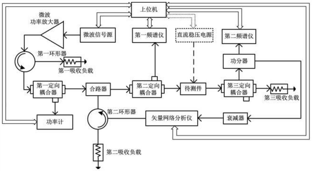
[0035] In order to make the technical solution of the present invention clearer, the present invention will be further described below through specific embodiments in conjunction with the accompanying drawings. This embodiment provides an automatic test system for high-power microwave effect experiments. The system includes: a high-power microwave injection unit, a reflected signal test unit, an S parameter real-time test unit, an output signal test unit, and a host computer.

[0036] The high-power microwave injection unit is used to generate high-power microwave signals, and includes sequentially cascaded microwave signal sources, solid-state microwave power amplifiers, first circulators, first directional couplers, combiners, and power meters.

[0037] The reflected signal testing unit is used for measuring the spectral power component of the reflected signal on the input port surface of the DUT, and includes a second directional coupler and a first spectrum analyzer.

[00...


PUM


Abstract

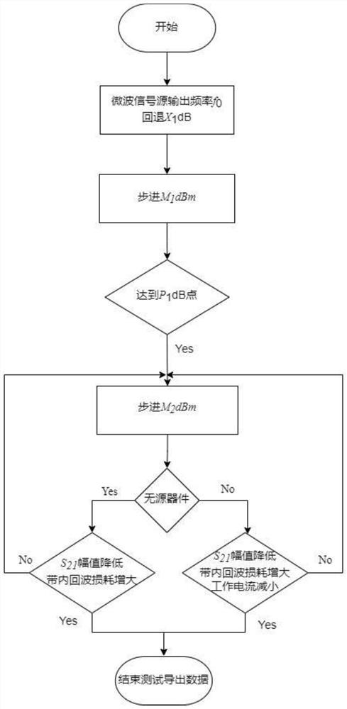
The invention discloses a high-power microwave effect experiment testing method and an automatic testing system, and belongs to the technical field of microwave effect testing. According to the method, whether the to-be-detected piece is damaged or not is judged by detecting key parameters of the to-be-detected piece before and after high-power microwave injection and detecting an S21 parameter, input power Pinc, reflection power Pr of an input end face and output power Pout of the to-be-detected piece in the high-power microwave injection process in real time, and the damage degree is graded and classified; the invention further provides an automatic testing system which comprises a high-power microwave injection unit, a reflected signal testing unit, an S parameter real-time testing unit, an output signal testing unit and an upper computer. According to the invention, the high-power microwave injection experiment is simplified, the automatic test is realized, the method is suitable for single-tone, dual-tone and multi-tone injection, the experiment test efficiency is improved, and the test safety is guaranteed.

Description

technical field [0001] The invention belongs to the technical field of microwave effect testing, and in particular relates to a high-power microwave effect experimental testing method and an automatic testing system. Background technique [0002] With the rapid development of advanced microelectronics technology, a large number of semiconductor devices with high integration, low power consumption and high sensitivity are widely used in electronic systems, which makes the trend of miniaturization, integration and multi-function of modern electronic equipment more and more Significantly, at the same time, it also exacerbates the vulnerability of electronic systems in complex electromagnetic environments. Among them, high-power microwaves are one of the important factors that cause damage to semiconductor devices. Therefore, the experimental research on the electromagnetic effect of high-power microwaves has important engineering application value in digging the damage mechani...

Claims


Application Information

Patent Timeline
Patent Type & Authority Applications(China)
IPC IPC(8): G01R29/08
Inventor 马春光赵俊宇张明文陈旭高源慈罗勇
Owner UNIV OF ELECTRONICS SCI & TECH OF CHINA
Learn More