Cold-formed thin-walled steel composite foam concrete wall

A technology of cold-formed thin-walled steel and concrete walls, applied to walls, building components, buildings, etc., can solve the problem of poor nailability of cold-formed thin-walled steel composite wall panels, weak external impact resistance of the overall structure, and impact damage resistance Poor capacity and other problems, to achieve the effect of not being easy to cavity effect, improving stiffness and improving seismic performance

Pending Publication Date: 2022-04-05
XI'AN UNIVERSITY OF ARCHITECTURE AND TECHNOLOGY
View PDF0 Cites 0 Cited by
  • Summary
  • Abstract
  • Description
  • Claims
  • Application Information

AI Technical Summary

Problems solved by technology

[0003] 1. The middle of the cold-formed thin-walled steel composite wallboard is basically a hollow structure, which is prone to "cavity effect" and loud noise
[0004] 2. When the cold-formed thin-walled steel system is applied in low-rise buildings, the overall structure's ability to resist external impacts is relatively weak, and it does not have the heavy feeling of the "Qin brick and Han tile" style favored by the public
[0005] 3. The skeleton of the cold-formed thin-walled steel system is composed of thin-walled components. The thinner the components, the greater the loss rate of corrosion and the short service life
[0006] 4. The cold-formed thin-walled steel system has poor impact resistance
[0007] 5. The cold-formed thin-walled steel composite wallboard has poor nailability, and it is not easy to hang heavy objects such as air conditioners

Method used


Image

  • Cold-formed thin-walled steel composite foam concrete wall
  • Cold-formed thin-walled steel composite foam concrete wall

Examples


Embodiment Construction

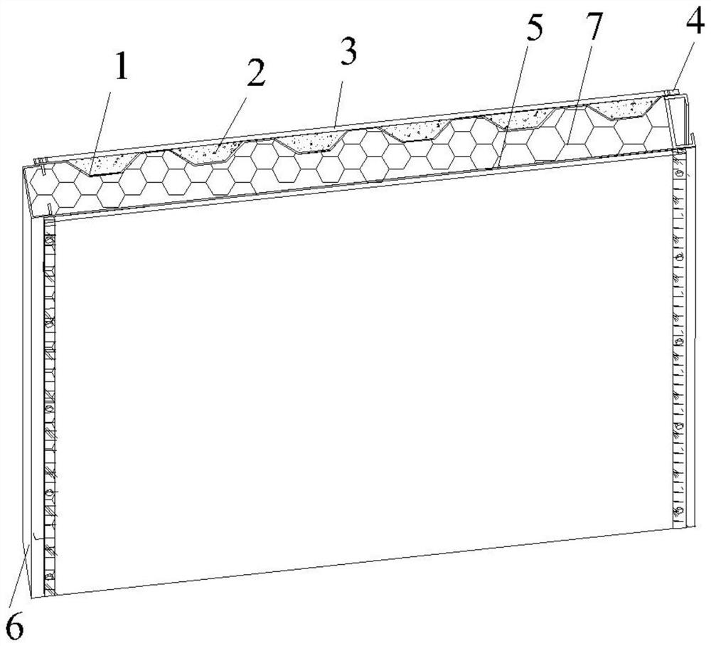
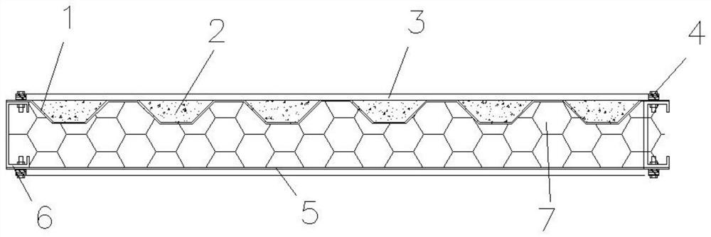
[0023] In order to enable those skilled in the art to better understand the solutions of the present invention, the following will clearly and completely describe the technical solutions in the embodiments of the present invention in conjunction with the drawings in the embodiments of the present invention. Obviously, the described embodiments are only The embodiments are a part of the present invention, not all embodiments, and are not intended to limit the scope of the present invention. Also, in the following description, descriptions of well-known structures and techniques are omitted to avoid unnecessarily obscuring the concepts disclosed in the present invention. Based on the embodiments of the present invention, all other embodiments obtained by persons of ordinary skill in the art without making creative efforts shall fall within the protection scope of the present invention.

[0024] The schematic diagrams of the structures according to the disclosed embodiments of th...


PUM

PropertyMeasurementUnit
widthaaaaaaaaaa

Abstract

The invention discloses a cold-formed thin-walled steel composite foam concrete wall which comprises a cold-formed thin-walled steel corrugated plate, a surface layer, a skin plate and C-shaped steel. The surface layer is located on one side of the cold-formed thin-walled steel corrugated plate, the skin plate is located on the other side of the cold-formed thin-walled steel corrugated plate, foam concrete is arranged between the surface layer and the cold-formed thin-walled steel corrugated plate, and the space between the cold-formed thin-walled steel corrugated plate and the skin plate is filled with light thermal insulation materials. And the end part of the skin plate is connected with the end part of the cold-formed thin-walled steel corrugated plate through the C-shaped steel, so that the wall body has the characteristics of high external impact resistance, long service life and high nailability, and meanwhile, a cavity effect is not easy to occur.

Description

technical field [0001] The invention belongs to the technical field of cold-formed thin-walled steel building construction, and relates to a cold-formed thin-walled steel composite foam concrete wall. Background technique [0002] Modern low-rise cold-formed thin-walled steel system houses mostly use composite walls composed of cold-formed thin-walled steel skeleton, concrete, wood boards, inner cavity filled with fireproof insulation cotton or rigid foamed polyurethane, etc., which are connected by bolts. Compared with the traditional brick-concrete structure or concrete structure wall, this kind of wall can achieve light weight and high strength, and the construction period is shorter, but there are also problems that cannot be ignored: [0003] 1. The middle of the cold-formed thin-walled steel composite wallboard is basically a hollow structure, which is prone to "cavity effect" and loud noise. [0004] 2. When the cold-formed thin-walled steel system is applied in low-...

Claims


Application Information

Patent Timeline
Patent Type & Authority Applications(China)
IPC IPC(8): E04B2/00E04B1/14E04C2/292E04C2/32
Inventor 于金光赵旭冯啸天
Owner XI'AN UNIVERSITY OF ARCHITECTURE AND TECHNOLOGY
Why Eureka
Try Eureka