
Flexible bearing for harmonic reducer and harmonic reducer

A technology of harmonic reducer and flexible bearing, applied in bearing components, shafts and bearings, rolling contact bearings, etc., can solve the problem of affecting the accuracy and transmission efficiency of harmonic reducer, bearing working surface scratching bearing accuracy, reducing bearing diameter Bearing capacity and other issues, to achieve good transmission accuracy, good restraint capacity, and improve the effect of stress

Active Publication Date: 2022-04-05
SHENZHEN INST OF ADVANCED TECH CHINESE ACAD OF SCI
View PDF5 Cites 0 Cited by
  • Summary
  • Abstract
  • Description
  • Claims
  • Application Information

AI Technical Summary

Problems solved by technology

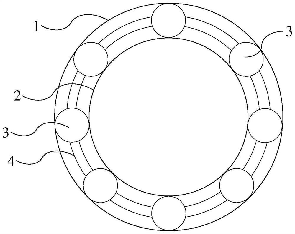
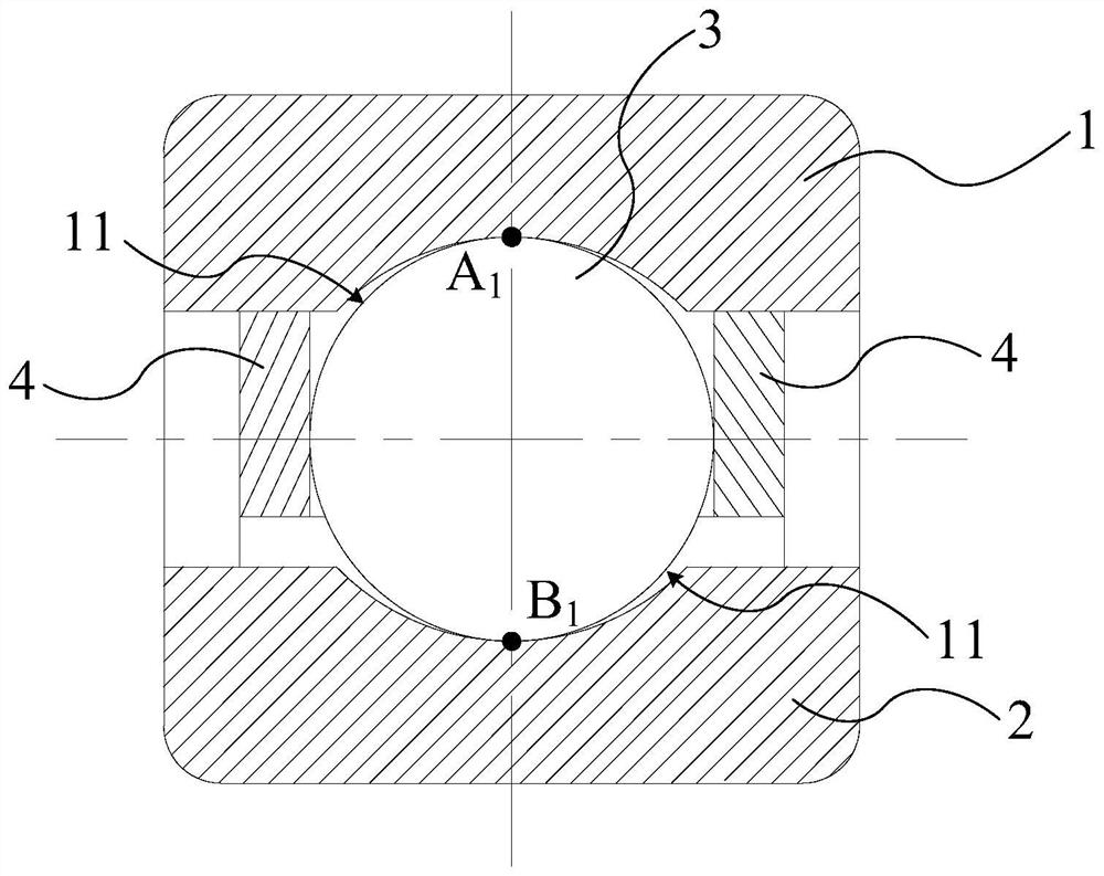
A kind of flexible bearing commonly used in harmonic reducers is a single row shallow groove radial ball bearing. The balls of this bearing have only one contact point with the groove-shaped raceway of the outer ring and the groove-shaped raceway of the inner ring. Therefore, the groove The spherical raceway has poor constraints on the balls, and the balls will generate a large amount of sliding components during motion, which will cause scratches on the bearing working surface and deterioration of bearing accuracy, affecting the accuracy and transmission efficiency of the harmonic reducer
[0004] In related technologies, multi-point contact bearings are also applied to harmonic reducers. The balls of this bearing form three or four contact points with the configuration raceways of the inner ring and outer ring, so that the sliding motion of the balls The weight is reduced, but at the same time it also reduces the radial load capacity of the bearing
During the working process of the harmonic reducer, the flexible bearing mainly bears the radial force. If the radial load capacity is insufficient, the bearing is prone to breakage and the service life is short

Method used


Image

  • Flexible bearing for harmonic reducer and harmonic reducer
  • Flexible bearing for harmonic reducer and harmonic reducer
  • Flexible bearing for harmonic reducer and harmonic reducer

Examples


Embodiment Construction

[0032] In order to make the purposes, technical solutions and advantages of the embodiments of the present application clearer, the technical solutions in the embodiments of the present application will be clearly and completely described below in conjunction with the drawings in the embodiments of the present application. Obviously, the described embodiments It is a part of the embodiments of this application, not all of them. Based on the embodiments in this application, all other embodiments obtained by persons of ordinary skill in the art without creative efforts fall within the protection scope of this application.

[0033] In the description of the present application, "plurality" means at least two, such as two, three, etc., unless otherwise specifically defined. In this application, terms such as "installation", "connection", "connection" and "fixation" should be interpreted in a broad sense, for example, it can be a fixed connection or a detachable connection, unless ...


PUM


Abstract

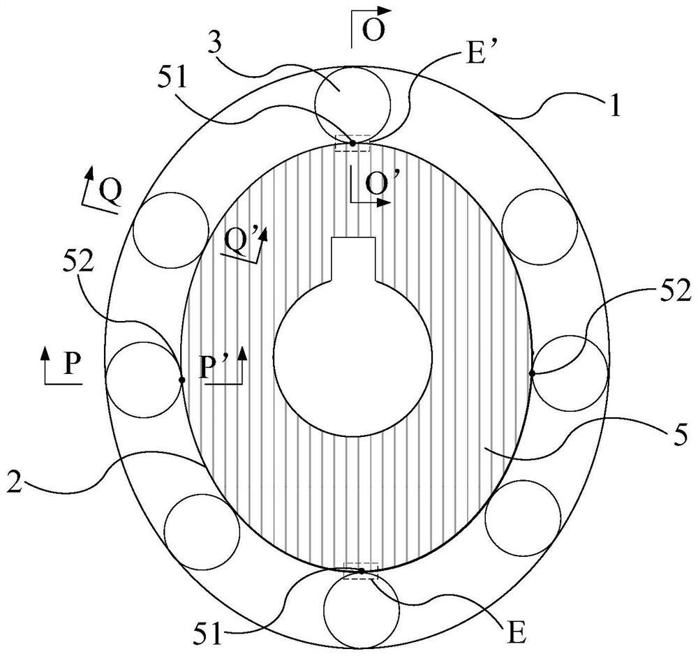
The invention provides a flexible bearing for a harmonic reducer and the harmonic reducer, the flexible bearing comprises an outer ring (1), an inner ring (2) and a rolling body (3) mounted between the outer ring (1) and the inner ring (2), and the outer ring (1) and the inner ring (2) are both provided with channels for accommodating the rolling body (3); the inner ring (2) is used for being arranged on the outer side of an oval cam (5) in a sleeving mode, and channels, located in the two ends of the oval cam (5) in the long axis direction, of the inner ring (2) and the rolling body (3) form a contact point. And two contact points are formed between the inner ring (2) and the rolling body (3), wherein the inner ring (2) is positioned in channels at other positions of the elliptical cam (5). According to the flexible bearing, the two ends in the long axis direction keep sufficient radial bearing capacity, meanwhile, the restraining capacity of the grooves of the flexible bearing on the balls is good, and the service life is longer.

Description

technical field [0001] The application belongs to the technical field of flexible bearings, and in particular relates to a flexible bearing for a harmonic reducer and a harmonic reducer. Background technique [0002] The harmonic reducer is mainly composed of three basic components: wave generator, flexible gear and rigid gear. Among them, the wave generator is composed of an elliptical cam and a flexible bearing assembled outside the cam. The harmonic reducer relies on the wave generator to make the flexible The gear produces controllable elastic deformation and meshes with the rigid gear to transmit motion and power. It has the characteristics of high transmission precision and large transmission speed ratio, and is widely used in aerospace, robotics and other fields. [0003] Flexible bearings are key parts and wearing parts in harmonic reducers. A kind of flexible bearing commonly used in harmonic reducers is a single row shallow groove radial ball bearing. The balls of...

Claims


Application Information

Patent Timeline
Patent Type & Authority Applications(China)
IPC IPC(8): F16C27/04F16C33/58F16H49/00F16H57/08
Inventor 柳冠伊何凯陈海伦
Owner SHENZHEN INST OF ADVANCED TECH CHINESE ACAD OF SCI
Learn More