Eureka AIR delivers breakthrough ideas for toughest innovation challenges, trusted by R&D personnel around the world.

Ion implantation apparatus and control method thereof

The technology of an ion implantation device and control method is applied in the field of ion implantation device and its control, and can solve problems such as liquid leakage and cracking of cooling pipes

Pending Publication Date: 2022-04-05
SHANGHAI INTEGRATED CIRCUIT RES & DEV CENT +1
View PDF0 Cites 0 Cited by
  • Summary
  • Abstract
  • Description
  • Claims
  • Application Information

AI Technical Summary

Problems solved by technology

Due to the low temperature, the silicon wafer stage will rotate according to the process requirements and drive the cooling tube to twist, which will easily cause the cooling tube to crack and cause problems such as liquid leakage.

Method used


Image

  • Ion implantation apparatus and control method thereof
  • Ion implantation apparatus and control method thereof
  • Ion implantation apparatus and control method thereof

Examples


Embodiment Construction

[0027] In order to make the purpose, technical solutions and advantages of the embodiments of the present invention clearer, the technical solutions in the embodiments of the present invention will be clearly and completely described below. Obviously, the described embodiments are part of the embodiments of the present invention, not all of them. the embodiment. Based on the embodiments of the present invention, all other embodiments obtained by persons of ordinary skill in the art without creative efforts fall within the protection scope of the present invention. Unless otherwise defined, the technical terms or scientific terms used herein shall have the usual meanings understood by those skilled in the art to which the present invention belongs. As used herein, "comprising" and similar words mean that the elements or items appearing before the word include the elements or items listed after the word and their equivalents, without excluding other elements or items.

[0028] ...


PUM


Abstract

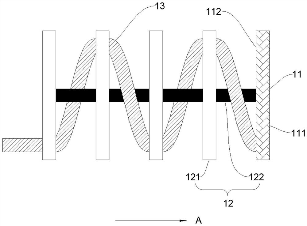
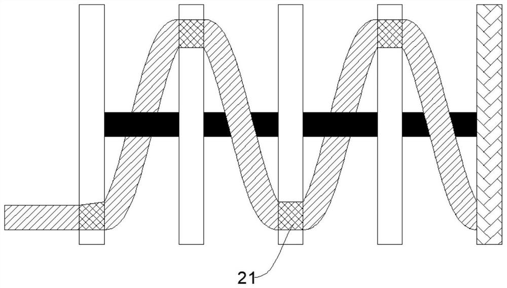
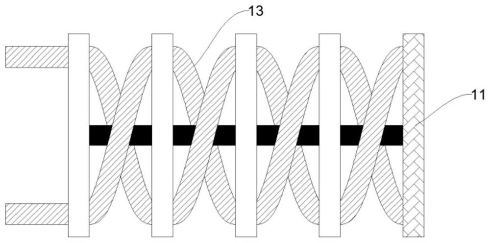
The invention provides an ion implantation device and a control method thereof. The ion implantation device comprises a loading part, a rotation control part, N rotating parts and a temperature control pipeline, wherein N is a positive integer greater than 1. The N rotating parts are sequentially and movably connected and are in communication connection with the rotating control part, the rotating control part controls at least one rotating part to rotate so as to drive the object carrying part to rotate, and large-angle rotation of the object carrying part can be achieved; and the temperature control pipelines spirally extend towards the carrying part, are arranged on the rotating parts and are arranged at the bottom of the carrying part, so that the temperature control pipelines are prevented from rotating by an overlarge angle in a single time, and the risks of cooling pipe cracking and liquid leakage are reduced.

Description

technical field [0001] The invention relates to the technical field of semiconductor device manufacturing, in particular to an ion implantation device and a control method thereof. Background technique [0002] With the rapid development of CMOS technology according to Moore's law, CMOS devices have higher and higher requirements for ultra-shallow junctions, and low-temperature implantation technology has developed accordingly. The traditional low-temperature ion implanter injects liquid nitrogen or liquid helium into the bottom of the stage carrying the silicon wafer through the cooling pipe to cool down the silicon wafer and perform the low-temperature ion implantation process. Due to the low temperature, the silicon wafer stage will rotate according to the process requirements and drive the cooling pipe to twist, which will easily cause the cooling pipe to crack and cause problems such as liquid leakage. [0003] Therefore, it is necessary to develop a novel ion implanta...

Claims


Application Information

Patent Timeline
Patent Type & Authority Applications(China)
IPC IPC(8): H01J37/317H01J37/20
CPCY02P70/50
Inventor 康晓旭
Owner SHANGHAI INTEGRATED CIRCUIT RES & DEV CENT
Why Eureka
Eureka Blog
Learn More