Optical module

An optical module and optical receiver technology, applied in the field of optical modules, can solve problems such as affecting the receiving sensitivity of optical modules

Pending Publication Date: 2022-04-05
HISENSE BROADBAND MULTIMEDIA TECH
View PDF0 Cites 0 Cited by
  • Summary
  • Abstract
  • Description
  • Claims
  • Application Information

AI Technical Summary

Problems solved by technology

When a 1.25G optical signal is input, the optical signal with a bandwidth greater than 1.25G and a bandwidth less than 10G can be conv

Method used


Image

  • Optical module
  • Optical module
  • Optical module

Examples


Embodiment Construction

[0025] The following will clearly and completely describe the technical solutions in the embodiments of the application with reference to the drawings in the embodiments of the application. Apparently, the described embodiments are only some of the embodiments of the application, not all of them. Based on the embodiments in this application, all other embodiments obtained by persons of ordinary skill in the art without making creative efforts belong to the scope of protection of this application.

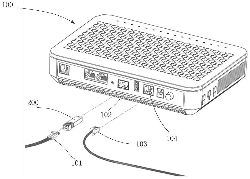
[0026] One of the core links of optical fiber communication is the mutual conversion of optical and electrical signals. Optical fiber communication uses optical signals carrying information to be transmitted in information transmission equipment such as optical fibers / optical waveguides, and the passive transmission characteristics of light in optical fibers / optical waveguides can be used to achieve low-cost, low-loss information transmission; and information processing equipment suc...


PUM


Abstract

The invention discloses an optical module, which comprises an optical sub-transceiver. The optical sub-transceiver module comprises an optical receiver. A photoelectric conversion assembly, an operational amplifier and an RC circuit are arranged in the optical receiver. The reverse input end of the operational amplifier is connected with the photoelectric conversion assembly and the first end of the RC circuit, and the output end of the operational amplifier is connected with the second end of the RC circuit. A logic control circuit and a limiting amplification circuit are arranged on the surface of the circuit board. The first end of the logic control circuit is connected with the output end of the operational amplifier, the second end of the logic control circuit is connected with the second end of the amplitude limiting amplification circuit, and the logic control circuit is used for selecting any sub-circuit in the RC circuit to be conducted according to the LOS signal. According to the optical module, the logic control circuit selects the first RC sub-circuit or the second RC sub-circuit to be conducted through the LOS signal output by the amplitude limiting amplification circuit, the transmission rate of the input optical signal is accurately matched with the bandwidth selected by the parameters of the first RC sub-circuit or the second RC sub-circuit, and therefore the signal transmission quality is improved, and the receiving sensitivity of the optical module is improved.

Description

technical field [0001] The present application relates to the technical field of communications, and in particular to an optical module. Background technique [0002] For the 10G optical module, it can receive optical signals with rates of 10G and 1.25G in different periods. The light emitting sub-module of the 10G optical module includes an avalanche diode, a transimpedance amplifier, a 10G limiting amplifier and a 1.25G limiting amplifier, wherein the photoelectric conversion component is electrically connected to the first end of the transimpedance amplifier, and the second end of the transimpedance amplifier They are electrically connected to the 10G limiting amplifier and the 1.25G limiting amplifier respectively, and the transimpedance amplifier includes not only a feedback resistor and a feedback capacitor electrically connected in parallel, but also an operational amplifier. [0003] In a traditional 10G optical module, the feedback resistor and the feedback capacit...

Claims


Application Information

Patent Timeline
IPC IPC(8): H04B10/40H04B10/25H04Q11/00G02B6/42
Inventor 王永辉金成浩路磊王健惠
Owner HISENSE BROADBAND MULTIMEDIA TECH
Why Eureka
Try Eureka