Dust removal spray tower for waste gas treatment
A technology for waste gas treatment and spray tower, applied in the field of spray tower for dust removal, can solve the problems of general waste heat recovery effect of spray tower for dust removal, inconvenient cleaning and collection of impurities, low resource utilization rate, etc. The effect of reducing corrosion damage and improving the treatment effect
- Summary
- Abstract
- Description
- Claims
- Application Information
AI Technical Summary
Problems solved by technology
Method used
Image

Examples
Embodiment 1
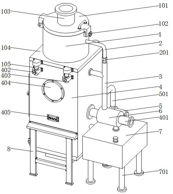
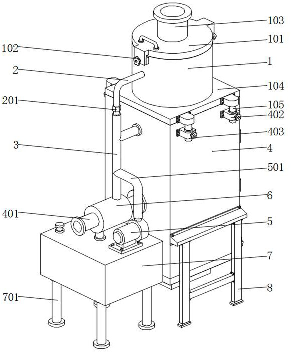
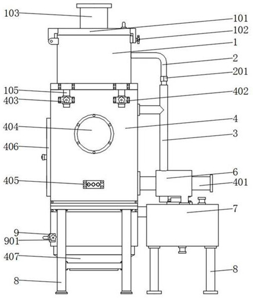
[0034] Such as Figure 1-7As shown, the present invention proposes a dust removal spray tower for waste gas treatment, including a first treatment box 1, a second treatment box 4 and a water tank 7, and the front and rear ends of the second treatment box 4 are all fixed by bolts A support frame 8 is installed to support the second treatment box 4 and improve stability. One side of the second treatment box 4 is provided with an air intake pipe 401, through which the exhaust gas is conveniently introduced into the second treatment box 4 for further processing. Processing, the outside of the intake pipe 401 is wrapped with a cooling box 6, the top of the cooling box 6 is provided with a delivery pipe 3, the bottom of the cooling box 6 is provided with a water tank 7, and the bottom of the water tank 7 is fixed with a support leg 701 by bolts for The water tank 7 is supported, and the water tank 7 communicates with the second treatment tank 4. The top of the water tank 7 is fixed ...
Embodiment 2
[0036] Such as Figure 1-7 As shown, the present invention proposes a dust removal spray tower for waste gas treatment. Compared with Embodiment 1, this embodiment also includes a fixed seat 104 fixed on the top of the second treatment box 4, and the fixed seat 104 The top of the top is fixed with the first treatment box 1, which can make the exhaust gas processed by the second treatment box 4 enter the second treatment box 4 for secondary treatment. Column 105, the front end and the rear end of the second treatment box 4 are all fixedly installed with the spacer seat 402 that cooperates with the spacer column 105 by bolts, the spacer column 105 can be inserted in the spacer seat 402, can be more conveniently fixed Seat 104 is installed, and the second fixing knob 403 is fixed between the limit seat 402 and the limit post 105, and it is also convenient to disassemble the fix seat 104, which is convenient for the operator to disassemble the first processing box 1 and the second...
PUM
 Abstract
Description
Claims
Application Information