Supercharge Your Innovation With Domain-Expert AI Agents!

Chipless cutting method and small U-shaped pipe forming process applying chipless cutting method

A cutting method and tube forming technology, applied in metal processing, manufacturing tools, other manufacturing equipment/tools, etc., can solve the problems of aggravating the manufacturing cost of small U-tubes, polluting the working environment, and alarming production losses, and save copper tube raw materials. , The effect of simplifying the process flow and saving copper tube raw materials

Pending Publication Date: 2022-04-08
虢建军
View PDF0 Cites 0 Cited by
  • Summary
  • Abstract
  • Description
  • Claims
  • Application Information

AI Technical Summary

Problems solved by technology

[0004] As we all know, the copper tube itself is expensive, and the existing cutting process with chips will cause a lot of waste of copper tubes. 100 meters of copper tube raw material used to manufacture small U tubes for air conditioners will result in a waste of 15 meters of copper tubes, and the copper tubes wasted in the production of small U tubes by a cutting equipment for one month can be bought in a new one Cutting equipment, therefore, this production loss is staggering, it is necessary to develop a chipless cutting method to replace the existing chip cutting process
[0005] In addition, the existing chip cutting process produces a large amount of cutting chips during the cutting process, so the small U tube after cutting needs to be washed and dried, making the forming process of the small U tube more efficient. complicated
Moreover, the cutting chips pollute the working environment, and it is necessary to install additional equipment and spend manpower to clean the cutting chips, which increases the manufacturing cost of the small U tube.

Method used


Image

  • Chipless cutting method and small U-shaped pipe forming process applying chipless cutting method
  • Chipless cutting method and small U-shaped pipe forming process applying chipless cutting method
  • Chipless cutting method and small U-shaped pipe forming process applying chipless cutting method

Examples


Embodiment Construction

[0041] The following will clearly and completely describe the technical solutions in the embodiments of the application with reference to the drawings in the embodiments of the application. Apparently, the described embodiments are only some of the embodiments of the application, not all of them. Based on the embodiments of the present application, all other embodiments obtained by persons of ordinary skill in the art without making creative efforts belong to the protection scope of the present application.

[0042] Unless otherwise defined, all technical and scientific terms used herein have the same meaning as commonly understood by one of ordinary skill in the technical field to which this application belongs. The terms used herein in the specification of the application are only for the purpose of describing specific embodiments, and are not intended to limit the application. As used herein, the term "and / or" includes any and all combinations of one or more of the associat...


PUM

PropertyMeasurementUnit
angleaaaaaaaaaa
lengthaaaaaaaaaa

Abstract

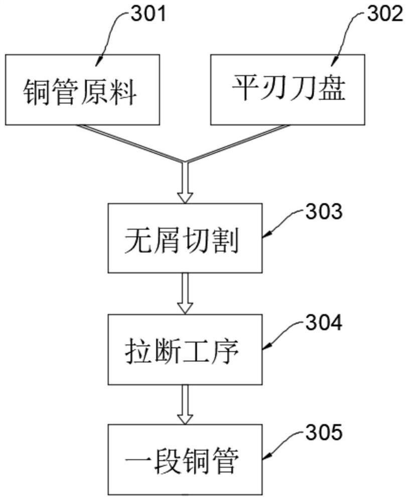
The invention belongs to the technical field of machining equipment of copper pipes for air conditioners, and provides a chipless cutting method and a small U-shaped pipe forming process applying the chipless cutting method.The chipless cutting method comprises the steps that a straight copper pipe raw material and a flat-edge cutter head are provided; chipless cutting is conducted, specifically, a tool mark is annularly cut along the periphery of the copper pipe raw material at a constant speed through the flat-edge cutter head; and a snapping process: snapping the copper pipe towards two opposite sides along the length direction of the copper pipe by taking the tool mark as the center to obtain a section of short and straight copper pipe. According to the chipless cutting method, almost no cutting chips are generated in the cutting process, and the purpose of saving copper pipe raw materials is achieved. According to the small U pipe forming technology applying the chipless cutting method, the technological process of an existing chipping cutting technology is simplified, copper pipe raw materials are saved, and the production cost is reduced.

Description

technical field [0001] The application belongs to the technical field of copper tube processing equipment for air conditioners, and in particular relates to a chipless cutting method and a small U-tube forming process using the chipless cutting method. Background technique [0002] The connection between the air conditioner indoor unit and the outdoor unit requires connecting materials. Copper pipes and aluminum pipes are commonly used to connect air conditioner indoor units and outdoor units. At present, the most commonly used air-conditioning connection material is air-conditioning copper pipes. Why use copper tubes, because the refrigerant ultimately absorbs heat in the evaporator and then releases heat in the condenser. The outside of the copper tube of the air conditioner is also connected to the heat sink, and the connecting tube passes through the refrigerant, which includes Freon, etc. , commonly known as snow species. Therefore, the quality of the copper tube use...

Claims


Application Information

Patent Timeline
Patent Type & Authority Applications(China)
IPC IPC(8): B23P15/00B23Q7/00B23P23/04
Inventor 虢建军
Owner 虢建军
Features
  • R&D
  • Intellectual Property
  • Life Sciences
  • Materials
  • Tech Scout
  • Unparalleled Data Quality
  • Higher Quality Content
  • 60% Fewer Hallucinations
Learn More