
Inclined laser range finder

A laser range finder and tilting technology, applied in the field of laser range finder, can solve the problems of vertical change of the pole, damage to the foundation of the pole, low accuracy of detection results, etc., so as to improve the practicality and accuracy. Effect

Pending Publication Date: 2022-04-08
张洪明
View PDF0 Cites 0 Cited by
  • Summary
  • Abstract
  • Description
  • Claims
  • Application Information

AI Technical Summary

Problems solved by technology

[0003] When the construction personnel need to measure the height of the poles on the rural roads, they need to use the laser rangefinder. Because the rural roads are in disrepair for a long time, it is easy to cause damage to the foundation of the poles, thus changing the verticality of the poles. However, the existing Most construction workers use hand-held laser rangefinders when measuring poles. Although this type of laser rangefinder is relatively light, its accuracy needs to be improved, especially for skewed poles. When measuring, it is difficult for construction personnel to make the angle detected by the laser rangefinder consistent with the angle of inclination of the line pole, resulting in low accuracy of detection results

Method used


Image

  • Inclined laser range finder
  • Inclined laser range finder
  • Inclined laser range finder

Examples


Embodiment Construction

[0021] The following will clearly and completely describe the technical solutions in the embodiments of the present invention with reference to the accompanying drawings in the embodiments of the present invention. Obviously, the described embodiments are only some, not all, embodiments of the present invention. Based on the embodiments of the present invention, all other embodiments obtained by persons of ordinary skill in the art without making creative efforts belong to the protection scope of the present invention.

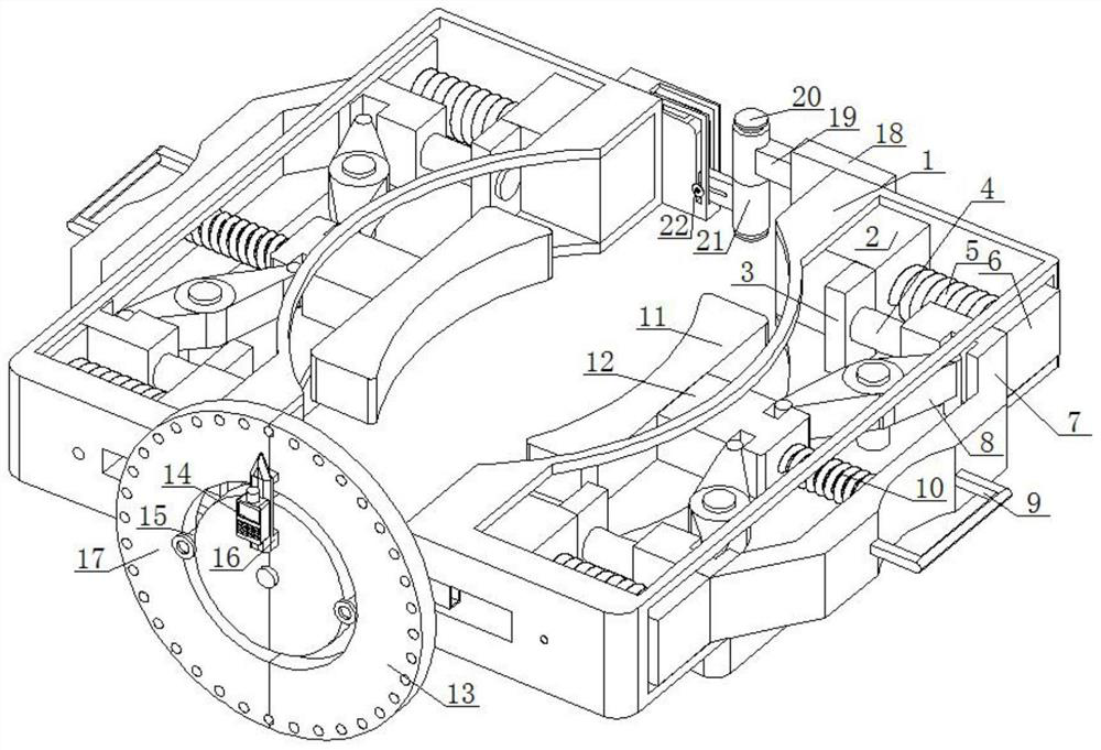
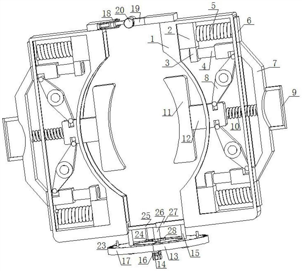
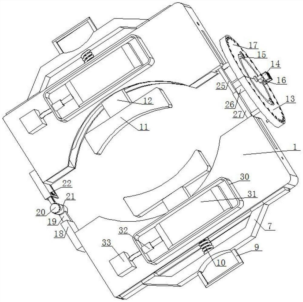
[0022] see Figure 1-5 , the present invention provides a technical solution: an inclined laser range finder, such as figure 1 As shown, two placement plates 1 are included, and the two placement plates 1 are symmetrically arranged left and right, and the corresponding sides of the two placement plates 1 are all provided with openings, and there is a rotating shaft near the rear side between the two placing boards 1 The outer sleeve is provided with a sleeve ...


PUM


Abstract

The inclined laser range finder comprises two placing plates, the two placing plates are arranged in a bilateral symmetry mode, the corresponding sides of the two placing plates are open, and a rotating shaft is arranged at the position, close to the rear side, between the two placing plates; through mutual cooperation of the compression spring, the placing block, the moving rod, the connecting plate, the moving frame, the rotating plate, a handle, a reset spring, a fixing plate, a clamping block and the like, the purpose of fixing the laser range finder on the outer side of a wire rod can be achieved, meanwhile, certain supporting force is provided, and compared with a handheld laser range finder, the laser range finder is more convenient to use. The clamping mechanism can be folded and stored through cooperation of a sleeve, a limiting circular plate, a rotating shaft, an L-shaped sliding groove, an L-shaped penetrating groove, a rolling rod and other components, and the practicability of the device is improved.

Description

technical field [0001] The invention relates to the technical field of laser range finders, in particular to an inclined laser range finder. Background technique [0002] The laser rangefinder is a comprehensive application of various technologies such as laser technology, electronic technology, single-chip microcomputer control technology, signal control and processing technology, and precision mechanical technology. The laser rangefinder is an instrument designed based on the principle of time-domain reflection to measure distances. Measurement of distances, and modern technological trends increasingly require good precision. [0003] When the construction personnel need to measure the height of the poles on the rural roads, they need to use the laser range finder. Because the rural roads are in disrepair for a long time, it is easy to cause damage to the foundation of the poles, thus changing the verticality of the poles. However, the existing Most construction workers ...

Claims


Application Information

Patent Timeline
Patent Type & Authority Applications(China)
IPC IPC(8): G01S17/08G01S7/481
Inventor 张洪明
Owner 张洪明
Learn More