
Method and device for detecting initial positions of rotors of multiple three-phase permanent magnet synchronous motors

A technology of rotor initial position and permanent magnet synchronous motor, applied in the direction of control of electromechanical transmission, control of generator, motor-generator control, etc., can solve the problems of detection result error, influence of detection accuracy of three-phase winding, etc., to improve detection accuracy Effect

Pending Publication Date: 2022-04-08
HUAZHONG UNIV OF SCI & TECH
View PDF0 Cites 0 Cited by
  • Summary
  • Abstract
  • Description
  • Claims
  • Application Information

AI Technical Summary

Problems solved by technology

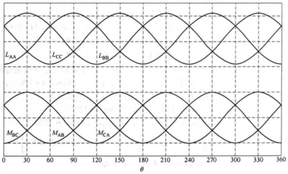
However, the high-frequency signal injection method, the voltage space vector method and the pulse voltage injection method all use the response current generated after the voltage injection to detect the rotor position, and the response current is related to the injected voltage and the inductance characteristics of the winding. Therefore, the three The inductance asymmetry of the phase winding will affect the detection accuracy of these three methods, and the more obvious the inductance asymmetry, the greater the error of the detection result

Method used


Image

  • Method and device for detecting initial positions of rotors of multiple three-phase permanent magnet synchronous motors
  • Method and device for detecting initial positions of rotors of multiple three-phase permanent magnet synchronous motors
  • Method and device for detecting initial positions of rotors of multiple three-phase permanent magnet synchronous motors

Examples


Embodiment 1

[0069] A method for detecting the initial position of the rotor of a multi-three-phase permanent magnet synchronous motor, such as Figure 4 shown, including:

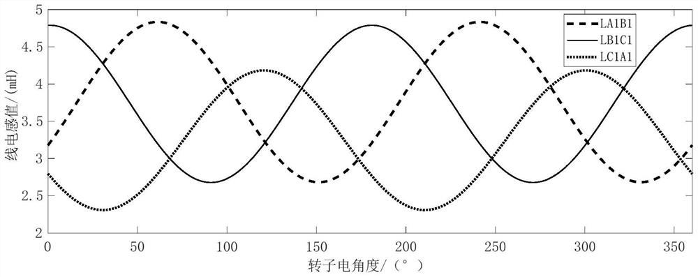
[0070] Select a set of three-phase windings in the motor, and detect the line inductance L of the A and C phases respectively CA , A, B two-phase line inductance L AB And the line inductance L of the B and C phases BC ;

[0071] Using the line inductance L AB or line inductance L BC The constant component L 0 , line inductance L AB or line inductance L BC The second harmonic component of L 2 , line inductance L CA constant component of and the line inductance L CA The second harmonic component of Line inductance L CA Make corrections to get the line inductance L' CA , and according to the line inductance L AB , line inductance L BC and line inductance L′ CA Calculate the rotor pole axial angle θ e ;Line inductance L AB , line inductance L BC and the line inductance L' CA The inductance value chan...

Embodiment 2

[0104] A rotor initial position detection device for a multi-three-phase permanent magnet synchronous motor, comprising:

[0105] The detection module is used to select a set of three-phase windings in the motor, and detect the line inductance L of the A and C phases respectively CA , A, B two-phase line inductance L AB And the line inductance L of the B and C phases BC ;

[0106] correction module for utilizing the line inductance L AB or line inductance L BC The constant component L 0 , line inductance L AB or line inductance L BC The second harmonic component of L 2 , line inductance L CA constant component of and the line inductance L CA The second harmonic component of Line inductance L CA Make corrections to get the line inductance L' CA , and according to the line inductance L AB , line inductance L BC and line inductance L′ CA Calculate the rotor pole axial angle θ e ;Line inductance L AB , line inductance L BC and the line inductance L' CA The in...


PUM


Abstract

The invention discloses a rotor initial position detection method and device for multiple three-phase permanent magnet synchronous motors, and belongs to the field of motor control, and the method comprises the steps: detecting three line inductors LX, LY and LZ in a set of three-phase windings; the LX and the LY symmetrically change along with the change of the position of the rotor; correcting the line inductance LZ by using the constant component L0 of the LX or LY and the constant component and the second harmonic component L2 and LZ to obtain the line inductance L 'Z, and then calculating the axial angle theta e of the rotor magnetic pole; the inductance values of LX, LY and L 'Z symmetrically change along with the change of the rotor position; two pulse voltage vectors which are equal in size, opposite in direction and close to the theta e direction and the theta e + pi direction respectively are injected into the three-phase windings respectively, and peak values of response currents in the three-phase windings are recorded respectively; if yes, the initial position angle of the rotor is judged to be theta e; if yes, the initial position angle of the rotor is judged to be theta e + pi; according to the invention, the detection precision of the initial position of the rotor of the multi-three-phase permanent magnet synchronous motor under the condition of asymmetric inductance can be improved.

Description

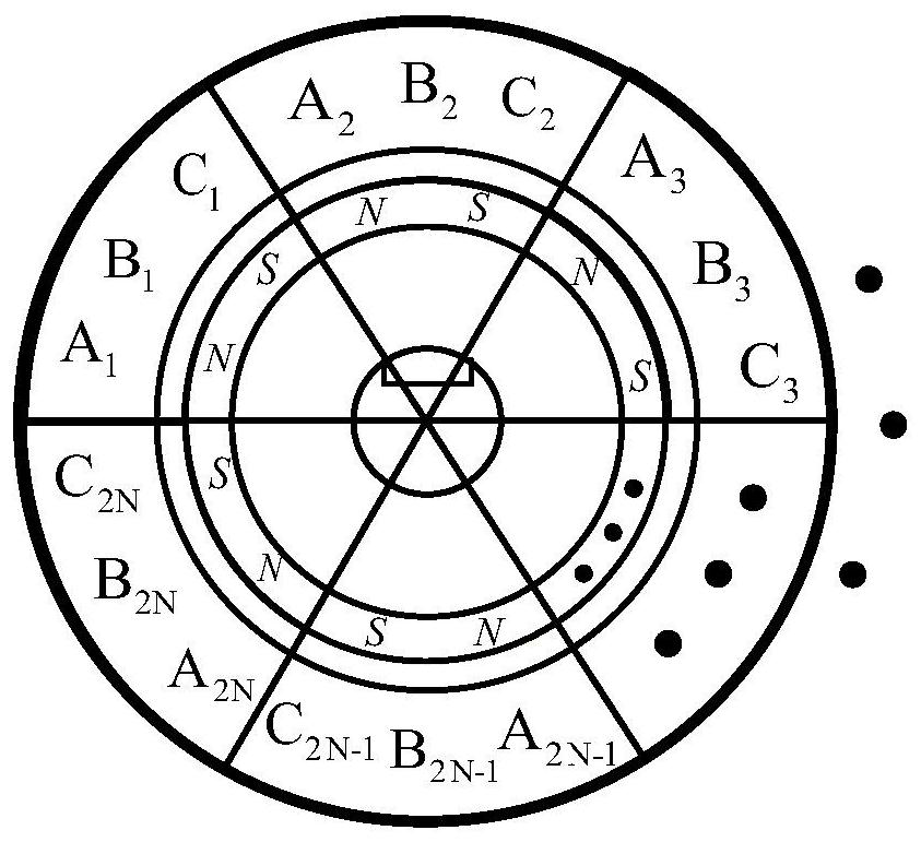
technical field [0001] The invention belongs to the field of motor control, and more specifically relates to a method and device for detecting the initial position of a rotor of a multi-three-phase permanent magnet synchronous motor. Background technique [0002] High-power is the development trend of AC drive system, and the design of high-power motors mostly adopts multi-phase design (the number of phases is greater than 3), which not only can reduce the capacity of the drive branch, but also has a certain fault-tolerant operation capability. Among all kinds of multi-phase permanent magnet synchronous motors, multi-three-phase permanent magnet synchronous motors have received more attention due to their close relationship with traditional three-phase permanent magnet synchronous motors. Multi-three-phase permanent magnet synchronous motors also need to detect the initial rotor position before starting. Accurate detection of the initial rotor position is of great significan...

Claims


Application Information

Patent Timeline
IPC IPC(8): H02P21/14H02P21/18H02P21/22H02P21/24H02P21/32H02P25/022
Inventor 刘自程石松蒋栋
Owner HUAZHONG UNIV OF SCI & TECH
Learn More