
SO3 removal device in sintering flue gas ultra-low emission system

A technology of sintering flue gas and exhaust system, which is applied in separation methods, dispersed particle separation, chemical instruments and methods, etc., and can solve problems such as insufficient contact between ammonia water and flue gas, incomplete removal of SO3, etc.

Pending Publication Date: 2022-04-12
HEBEI ZHONGKE LANGBO ENVIRONMENTAL PROTECTION TECH CO LTD
View PDF7 Cites 0 Cited by
  • Summary
  • Abstract
  • Description
  • Claims
  • Application Information

AI Technical Summary

Problems solved by technology

[0003] The present invention proposes SO in the sintering flue gas ultra-low emission system 3 The removal device solves the problem that the ammonia water and the flue gas cannot be fully contacted when the removal tower of the related technology is used, resulting in SO in the flue gas 3 remove imperfections

Method used


Image

  • SO3 removal device in sintering flue gas ultra-low emission system
  • SO3 removal device in sintering flue gas ultra-low emission system
  • SO3 removal device in sintering flue gas ultra-low emission system

Examples


Embodiment Construction

[0032] The technical solutions in the embodiments of the present invention will be clearly and completely described below in conjunction with the embodiments of the present invention. Apparently, the described embodiments are only some of the embodiments of the present invention, not all of them. Based on the embodiments of the present invention, all other embodiments obtained by persons of ordinary skill in the art without making creative efforts all involve the protection scope of the present invention.

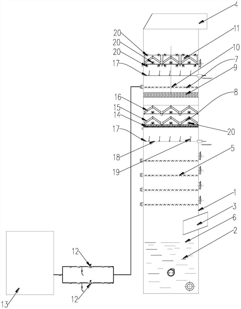
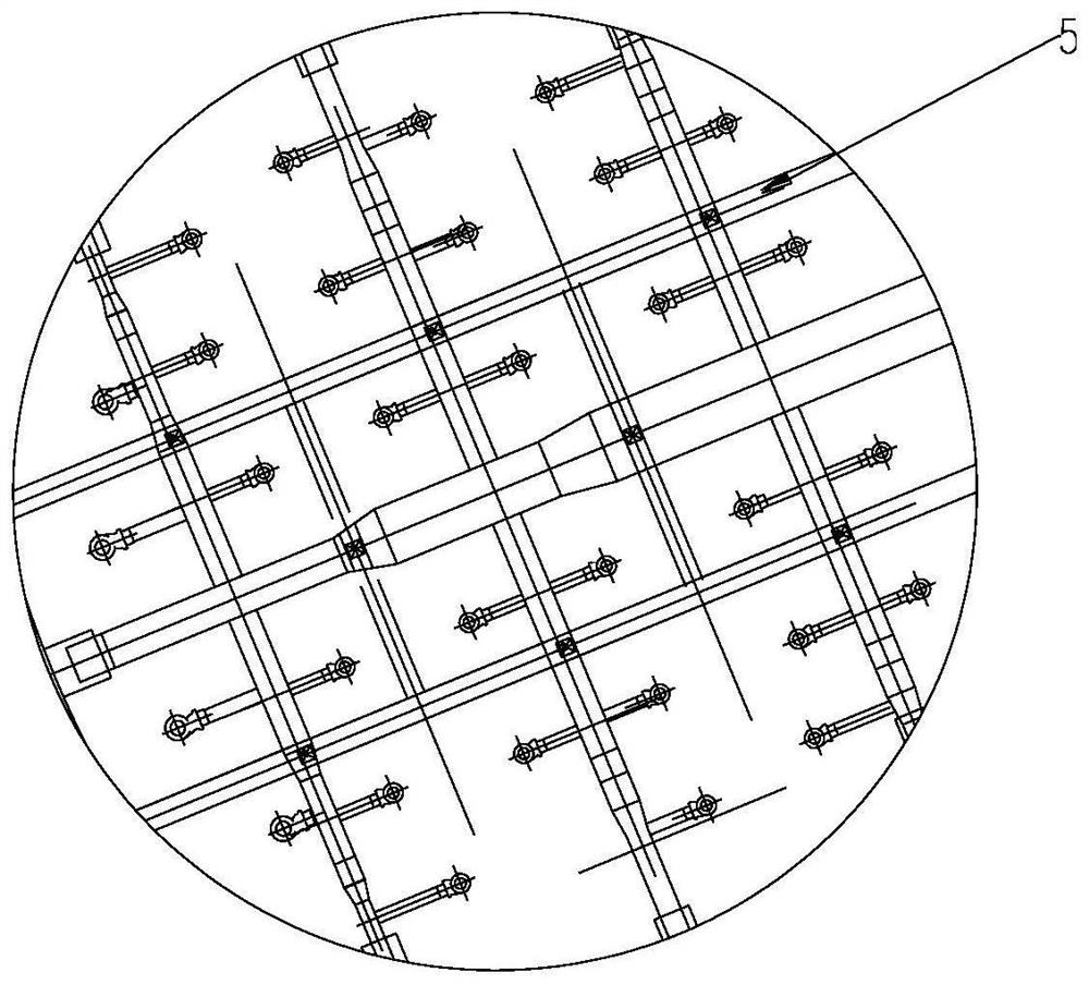
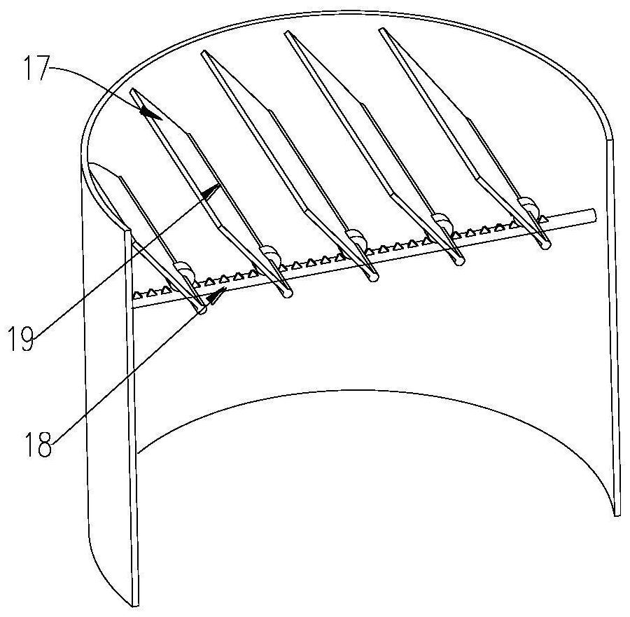
[0033] Such as Figure 1 ~ Figure 3 As shown, this example proposes

[0034] SO in sintering flue gas ultra-low emission system 3 Removal devices, including:

[0035] The removal tower 1, the bottom is used to hold the alkaline slurry 2, has a flue gas inlet 3 and a flue gas outlet 4,

[0036] The absorption spray layer 5 is arranged inside the removal tower 1, the absorption spray layer 5 communicates with the alkaline slurry 2 through a circulation pump, and the flue g...


PUM


Abstract

The invention relates to the technical field of desulfurization equipment, and provides a SO3 removal device in a sintering flue gas ultra-low emission system, which comprises a removal tower, the bottom of the removal tower is used for containing alkaline slurry, the removal tower is provided with a flue gas inlet and a flue gas outlet, an absorption spraying layer is arranged in the removal tower, and the absorption spraying layer is communicated with the alkaline slurry through a circulating pump. The flue gas inlet is located between the liquid level of the alkaline slurry and the absorption spraying layer, the SO3 removal layer is arranged in the removal tower, is located above the absorption spraying layer and is located below the flue gas outlet, the SO3 removal layer comprises a pre-demisting layer, a filler layer, an ammonia water spraying layer and a tail end demisting layer which are sequentially arranged from bottom to top, the ammonia water spraying layer is communicated with an ammonia water storage tank through a delivery pump, and the tail end demisting layer is communicated with the tail end of the absorption spraying layer. After passing through the filler layer, the flue gas is in contact with the ammonia water sprayed by the ammonia water spraying layer. The filler layer is additionally arranged, so that the problem that the SO3 in the flue gas is not completely removed due to the fact that ammonia water and the flue gas cannot be fully contacted when the removal tower in the related technology is used is solved.

Description

technical field [0001] The invention relates to the technical field of desulfurization equipment, in particular, it relates to SO in sintering flue gas ultra-low emission system 3 Remove device. Background technique [0002] In the iron and steel production industry, the sintering process is usually used. Sintering refers to the transformation of powdery materials into dense bodies. It is a traditional process. People have long used this process to produce ceramics, powder metallurgy, refractory materials, super High-temperature materials, etc. Generally speaking, after the powder is formed, the dense body obtained by sintering is a polycrystalline material, and its microstructure is composed of crystals, glass bodies and pores. Generally, a large amount of flue gas will be generated during the sintering process, and the flue gas will contain certain harmful substances. When the flue gas is treated, the removal tower is usually used, but the existing removal tower has certa...

Claims


Application Information

Patent Timeline
IPC IPC(8): B01D53/78B01D53/80B01D53/50B01D53/75
Inventor 默良博姚国瑞李自尚兰建超周建锋阮剑青
Owner HEBEI ZHONGKE LANGBO ENVIRONMENTAL PROTECTION TECH CO LTD
Learn More