Main beam unit with UHPC formwork structure, main beam structure and construction method of main beam structure

A formwork and main beam technology, applied in bridges, bridge construction, bridge parts, etc., can solve the problems of low strength of prefabricated bridges, complicated on-site construction procedures, inconvenient transportation and installation, etc., and achieve simplified construction procedures, simple construction methods, Construct simple effects

Active Publication Date: 2022-04-12
HUNAN UNIV
View PDF9 Cites 0 Cited by
  • Summary
  • Abstract
  • Description
  • Claims
  • Application Information

AI Technical Summary

Problems solved by technology

Generally speaking, prefabricated bridges mainly have pain points such as low strength, heavy weight, inconvenient transportation and installation, and large amount of on-site welding. At the same time, joints are generally prone to damage, and on-site construction procedures are more complicated.

Method used


Image

  • Main beam unit with UHPC formwork structure, main beam structure and construction method of main beam structure
  • Main beam unit with UHPC formwork structure, main beam structure and construction method of main beam structure
  • Main beam unit with UHPC formwork structure, main beam structure and construction method of main beam structure

Examples


Embodiment 1

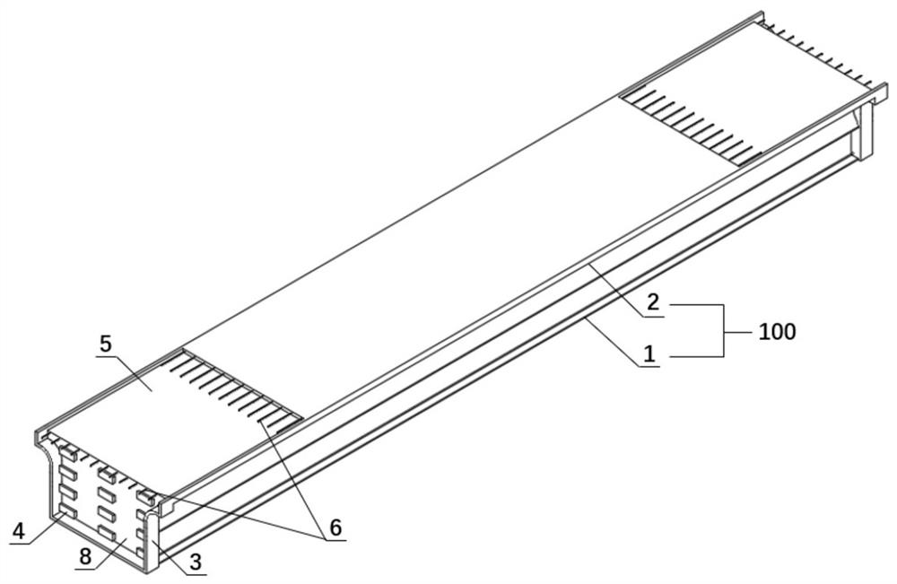
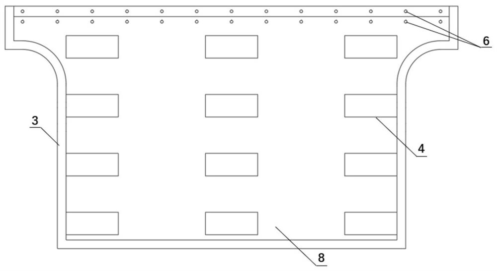
[0050] Such as Figure 1-Figure 6 As shown, the main beam unit (type I) with UHPC formwork structure of this embodiment includes a main beam body 100, at least one longitudinal bridge end of the main beam body 100 is provided with a UHPC formwork structure, and the UHPC formwork structure It includes a riser 8 located at the end of the girder body 100 , and the side and bottom of the riser 8 extend away from the girder body 100 to form a longitudinal bridge extension plate 3 .

[0051] In this embodiment, the riser 8 is provided with a plurality of tooth keys 4 on the surface away from the main girder body 100 . Specifically, the trapezoidal tooth key includes an upper top surface and a lower bottom surface, the area of ​​the upper top surface is larger than the area of ​​the lower bottom surface, the lower bottom surface is close to the vertical plate, and the upper top surface is away from the vertical plate; the distance between adjacent trapezoidal tooth keys in the height...

Embodiment 2

[0063] Such as Figure 8-Figure 12 As shown, the main beam unit (Type II) with UHPC formwork structure in this embodiment includes a main beam body 100, at least one longitudinal bridge end of the main beam body 100 is provided with a UHPC formwork structure, and the UHPC formwork structure It includes a riser 8 located at the end of the girder body 100 , and the side and bottom of the riser 8 extend away from the girder body 100 to form a longitudinal bridge extension plate 3 .

[0064] In this embodiment, the riser 8 is provided with a plurality of tooth keys 4 on the surface away from the main girder body 100 , and its specific arrangement can be the same as that of the first embodiment.

[0065] In this embodiment, the main beam body 100 is a steel-UHPC composite beam, and the steel-UHPC composite beam includes a steel beam and a UHPC beam, the steel beam is a welded I-beam 10, and the UHPC beam is a rectangular flat beam 9; the welded I-beam The upper flange of 10 is pro...

Embodiment 3

[0070] Such as Figure 13-Figure 16 As shown, the main beam unit (Type III) with UHPC formwork structure in this embodiment includes a main beam body 100, at least one longitudinal bridge end of the main beam body 100 is provided with a UHPC formwork structure, and the UHPC formwork structure It includes a riser 8 located at the end of the girder body 100 , and the side and bottom of the riser 8 extend away from the girder body 100 to form a longitudinal bridge extension plate 3 .

[0071]In this embodiment, the riser 8 is provided with a plurality of tooth keys 4 on the surface away from the main girder body 100 , and its specific arrangement can be the same as that of the first embodiment.

[0072] In this embodiment, the main beam body 100 is a UHPC single beam, and the UHPC single beam is a π-shaped beam 2 . Specifically, the π-shaped beam 2 includes a top plate 21, a pair of arc-shaped webs 22 and a pair of bottom plates 23, the bottom plate 23 is arranged at the bottom ...


PUM

PropertyMeasurementUnit
Thicknessaaaaaaaaaa
Diameteraaaaaaaaaa
Heightaaaaaaaaaa

Abstract

The invention discloses a main beam unit with UHPC (Ultra High Performance Concrete) formwork structures, which comprises a main beam body, at least one longitudinal bridge direction end part of the main beam body is provided with the UHPC formwork structures, and each UHPC formwork structure comprises a vertical plate positioned at the end part of the main beam body; the side edges and the bottom edges of the vertical plates extend in the direction away from the main beam body to be provided with longitudinal-bridge-direction extension plates. The invention further provides a main beam structure and a construction method of the main beam structure. The UHPC formwork structure is arranged at the end of the main beam body, a ready-made formwork is provided for a pier top cast-in-place joint structure, the formwork of the joint structure does not need to be erected on a construction site, ultra-high performance concrete can be directly cast in place at the joint, construction is convenient, and rapid construction of a bridge structure is facilitated.

Description

technical field [0001] The invention belongs to the field of bridges, and in particular relates to a main beam unit, a main beam structure and a construction method thereof. Background technique [0002] Small and medium-span prefabricated bridges play a pivotal role in my country's bridge construction. According to statistics from the Ministry of Transport, by the end of 2020, there were about 786,400 small and medium-span bridges across the country, accounting for 86.2% of highway bridges, an increase of 34,500 compared with 2019. In the face of such a large stock market and incremental market, promoting the development of prefabricated small and medium-span bridges is of great significance for changing bridge construction methods, improving bridge engineering quality, and shortening bridge construction periods. [0003] At present, there are three main types of prefabricated bridges: prefabricated concrete beams, prefabricated steel-concrete composite beams, and prefabri...

Claims


Application Information

Patent Timeline
IPC IPC(8): E01D2/00E01D19/00E01D21/00
CPCE01D2/00E01D19/00E01D21/00
Inventor 邵旭东应李溶君赵旭东
Owner HUNAN UNIV
Why Eureka
Try Eureka