Permeable hidden drainage ditch and construction method thereof
A construction method and drainage ditch technology, applied in the directions of separation methods, drainage structures, chemical instruments and methods, etc., can solve the problem that the sponge city cannot fully utilize and allocate rainwater and groundwater, and cannot play the role of water storage and drainage in the sponge city. Too simple and other problems to achieve good landscape effect, prevent pollution transfer, and keep clean
- Summary
- Abstract
- Description
- Claims
- Application Information
AI Technical Summary
Problems solved by technology
Method used
Image
Examples
Embodiment 1
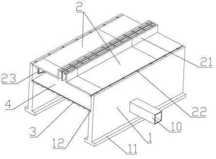
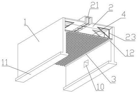
[0045] The embodiment of the present invention discloses a permeable concealed drainage ditch, referring to Figure 1-5 , including a drainage ditch body 1, the drainage ditch body 1 is installed in the base soil layer 7, a top plate 2 is installed on the top of the drainage ditch body 1, and a water inlet tank 21 is arranged on the top plate 2, and the drainage ditch body 1 A water diversion cylinder 10 is connected to the side, and the inner bottom of the drainage ditch body 1 is connected to the base soil layer 7 and is paved with pebbles 5 , and a supporting screen plate 3 is arranged in the middle of the drainage ditch body 1 .
[0046] A method for constructing a permeable concealed drainage ditch, comprising the following construction steps:
[0047]Step 1: Calculate the cross-sectional area of the drainage ditch required by the annual average precipitation and the highest precipitation, prefabricate the drainage ditch body 1, support sieve plate 3 and roof 2 accordin...
Embodiment 2
[0054] Increase on the basis of embodiment 1:
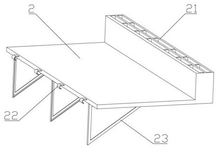
[0055] refer to Figure 1-5 One side of the top plate 2 is hung on the hinge shaft 13 at the top of the drain body 1 through the hinge hook 22, and the other side of the top plate 2 is provided with a water inlet tank 21, and the top of the water inlet tank 21 is 5-15cm higher than the top of the top plate 2 .
[0056] The bottom of the top plate 2 is provided with a triangular support 23 close to the drain body 1, and when the top plate 2 is laid flat, the vertical side of the triangular support 23 is close to the vertical surface of the drain body 1.
[0057] The supporting sieve plate 3 is placed on the boss 12 on the drainage ditch body 1, and the supporting sieve plate 3 is covered with a permeable geotextile 4, and both sides of the permeable geotextile 4 are close to the vertical surface of the drainage ditch body 1.
Embodiment 3
[0059] Increase on the basis of embodiment 2:
[0060] The earthwork excavation described in step 2 adopts a bucket of the same shape as the excavated trench for one-time excavation and formation, and reserves backfill grooves on both sides at the same time, between the drainage ditch body 1 and the urban water storage facilities and water facilities Dig out the water diversion tube 10 to pre-bury the ditch and bury the water diversion tube 10 to communicate with the drainage ditch body 1 and the urban water storage facilities and water use facilities.
[0061] After the pebbles 5 are laid, the pebbles 5 are vibrated and compacted, and the compacted pebbles 5 are tested for water permeability.
[0062] The supporting sieve plate 3 is installed in sections, and the joints are smoothed.
PUM
 Abstract
Description
Claims
Application Information
 - R&D
- Intellectual Property
- Life Sciences
- Materials
- Tech Scout
- Unparalleled Data Quality
- Higher Quality Content
- 60% Fewer Hallucinations
Browse by: Latest US Patents, China's latest patents, Technical Efficacy Thesaurus, Application Domain, Technology Topic, Popular Technical Reports.
© 2025 PatSnap. All rights reserved.Legal|Privacy policy|Modern Slavery Act Transparency Statement|Sitemap|About US| Contact US: help@patsnap.com


