
Throttle orifice plate suitable for high-temperature exhaust system

A technology of throttling orifice and exhaust system, which is applied in pipeline system, gas/liquid distribution and storage, pipe/pipe joint/fitting, etc., which can solve the problems of high replacement cost, back pressure adjustment, long stabilization time, and back pressure The problem of high cost of regulating valves, to achieve the effect of simple structure and low cost

Pending Publication Date: 2022-04-12
BEIJING AVIATION FEIFANG MACHINERY EQUIP FACTORY
View PDF0 Cites 0 Cited by
  • Summary
  • Abstract
  • Description
  • Claims
  • Application Information

AI Technical Summary

Problems solved by technology

Valves made of high temperature alloy are limited by the temperature of the material itself and the temperature of the seal, and are generally used in an environment where the exhaust temperature does not exceed 1000°C; the solution of spraying water in front of the valve to cool down + common material valves requires a high-pressure water spray system And the water spray device, and the amount of adjustment is large during use and is affected by the phase change process of the spray water, resulting in long back pressure adjustment and stable time
The above two back pressure adjustment schemes are affected by the high temperature exhaust, and the easily damaged equipment is the valve. The cost of the back pressure adjustment type valve is high, and the replacement cost after damage is high

Method used


Image

  • Throttle orifice plate suitable for high-temperature exhaust system
  • Throttle orifice plate suitable for high-temperature exhaust system

Examples


Embodiment Construction

[0022] The disclosed examples will be described more fully with reference to the accompanying drawings, in which some, but not all, of the disclosed examples are shown. In fact, many different examples may be described and should not be construed as limited to those set forth herein. Rather, these examples are described so that this disclosure will be thorough and complete, and will fully convey the scope of the disclosure to those skilled in the art.

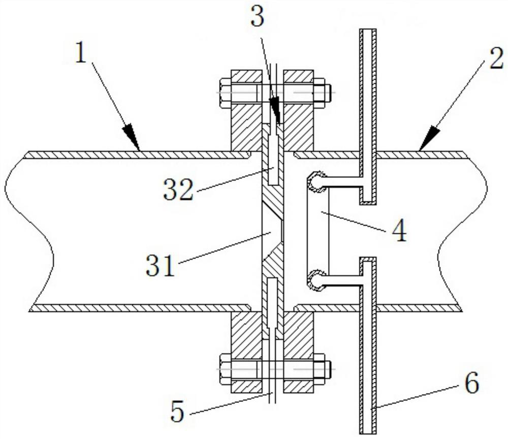
[0023] A specific embodiment is: provide a throttling orifice suitable for a high-temperature exhaust system, the throttling orifice is installed between the outlet of the high-temperature exhaust pipe and the inlet of the low-temperature exhaust pipe, and the high-temperature exhaust is subjected to the throttling orifice throttling effect;

[0024] The throttling orifice has a central throttling hole, the throttling orifice has an annular cooling cavity, the annular cooling cavity is concentrically arranged with the central ...


PUM


Abstract

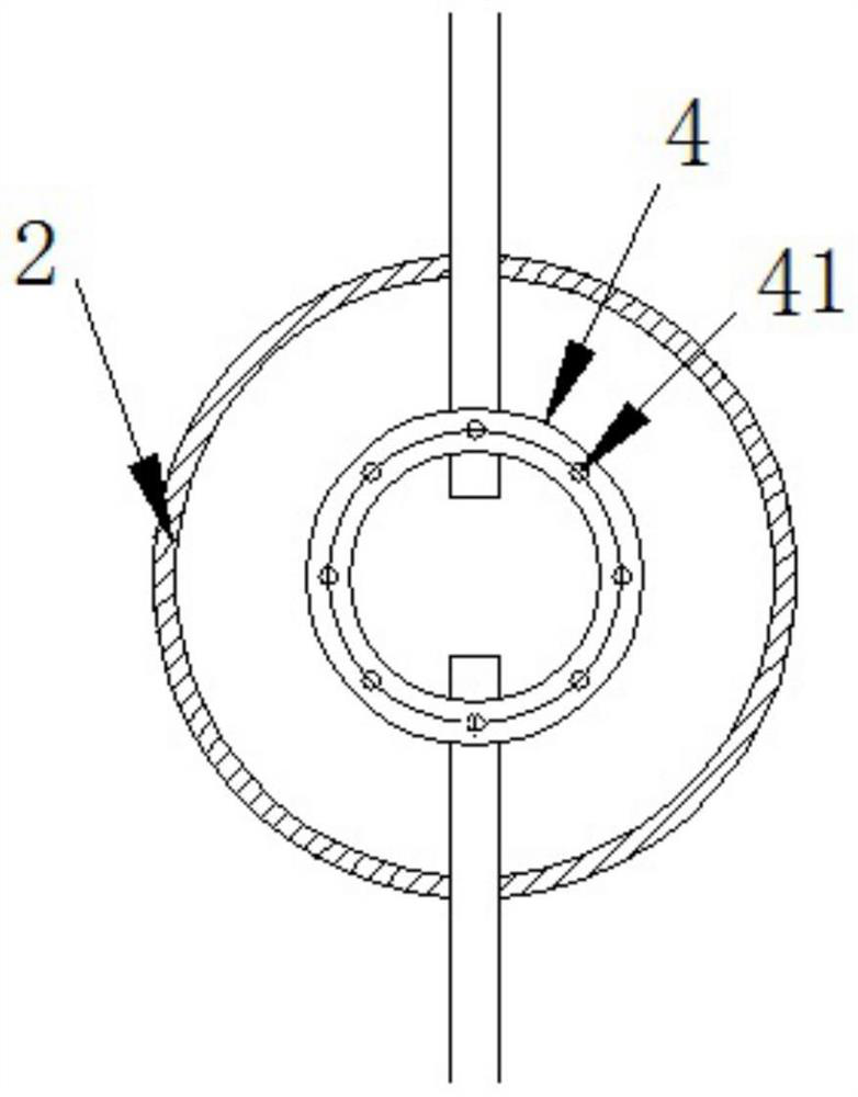
The invention relates to a throttling orifice plate suitable for a high-temperature exhaust system. The throttling orifice plate is provided with a center throttling hole and an annular cooling cavity, the annular cooling cavity and the center throttling hole are concentrically arranged, the throttling orifice plate is connected with a first circulating cooling pipe, and the first circulating cooling pipe is communicated with the annular cooling cavity; the cooling cavity and the first circulating cooling pipe are filled with a cooling medium; a spraying ring is arranged in the low-temperature exhaust pipeline, the spraying ring is an annular pipe, a plurality of spraying holes are formed in the annular pipe, the spraying direction of the spraying holes faces the back face of the throttling orifice plate, and the spraying holes are used for cooling the throttling orifice plate; and a cooling water pipe penetrates into the low-temperature exhaust pipeline from the outside of the low-temperature exhaust pipeline and is communicated to the annular pipe. The water-cooled pore plate is used as a throttling element, and water is used as a cooling medium of the pore plate, so that the pore plate can bear extremely high exhaust temperature.

Description

technical field [0001] The invention relates to the technical field of testing equipment, in particular to a throttling orifice plate for ground testing high-temperature exhaust of aero-engines and gas turbines. Background technique [0002] At present, in the development process of aero-engines and gas turbines, ground test equipment plays an irreplaceable role. By simulating the real environmental conditions or modeling conditions of aero-engine and gas turbine components on the ground test equipment, it can be obtained quickly and at low cost. The performance parameters of the components are used for the adjustment and optimization of the design scheme. [0003] It is used for testing equipment for components such as combustion chambers and turbine blades. The exhaust gas is characterized by high temperature, and the exhaust temperature can reach 1700°C or even higher. When carrying out experimental research on components such as combustion chambers and turbine blades, i...

Claims


Application Information

Patent Timeline
IPC IPC(8): F16L55/02F16L53/70F17D5/00
Inventor 付镇柏高晓会宋航
Owner BEIJING AVIATION FEIFANG MACHINERY EQUIP FACTORY
Learn More