
UB hanging plate automatic bending machine

A bending machine, automatic technology, applied in the direction of feeding device, positioning device, storage device, etc., can solve the problems of troublesome bending engineering, low work efficiency, cumbersome process, etc., to reduce work intensity and difficulty, and improve production efficiency. , the effect of simple and easy work

Pending Publication Date: 2022-04-15
SICHUAN XISHU ELECTRIC POWER FITTING GRP
View PDF0 Cites 0 Cited by
  • Summary
  • Abstract
  • Description
  • Claims
  • Application Information

AI Technical Summary

Problems solved by technology

This bending method requires two bending machines and at least two operators each time. The process is cumbersome and the work efficiency is low. In addition, the workload of the operators is large during the bending process, and the bending project is troublesome. , increasing the difficulty of the operator's work, and the risk factor is large, which cannot guarantee the safety of the operator well, and cannot adapt to different types of hanging board processing

Method used


Image

  • UB hanging plate automatic bending machine
  • UB hanging plate automatic bending machine
  • UB hanging plate automatic bending machine

Examples


Embodiment 1

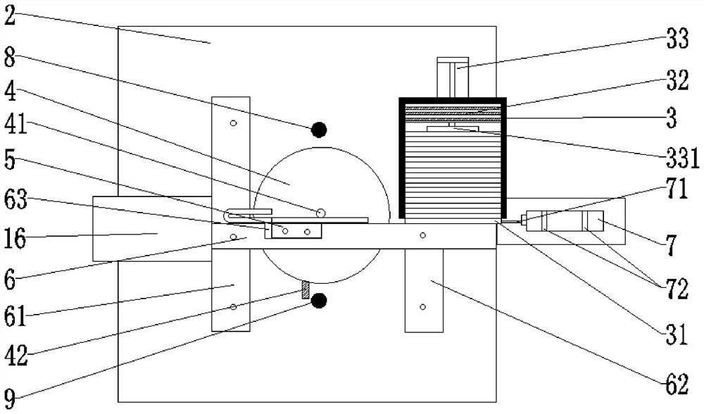
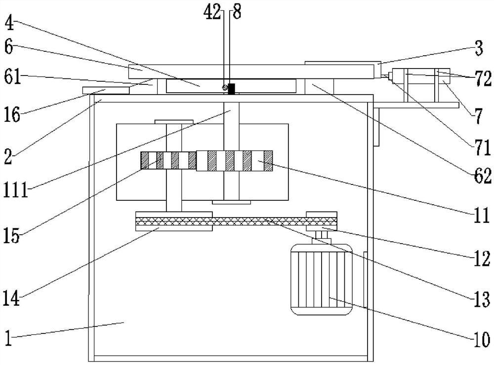
[0026] Embodiment 1: as figure 1 , figure 2 A UB hanging plate automatic bending machine shown is composed of a power device 1, a bending part and a frame 2, wherein the power device 1 is installed on the lower side of the frame 2, and the bending part is located above the power device 1. The output shaft 111 of the power device 1 is connected to the curved part, wherein the curved part includes a material box 3, a turntable 4, a moving module 5, and a fixed module 6, wherein: the center of the surface of the turntable 4 is provided with a vertical shaft 41, and the moving module 5 Fixed on the turntable 4, can rotate together with the turntable 4, and is installed on the first fixed mold base 61 one end of frame 2 mesa surface grooves 63 gap adaptation, the magazine 3 is fixed on the second One end of the two fixed mold bases 62, its discharge port 31 is directly opposite to the inner surface of the fixed module 6, and the fixed module 6 is fixed by the first fixed mold bas...

Embodiment 2

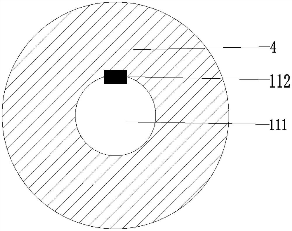
[0027] Embodiment 2: as figure 2 , image 3 , Figure 4 As shown, on the basis of Embodiment 1, this equipment optimally designs the connection between the power unit 1 and the turntable 4, that is, the output shaft 111 of the power unit 1 is connected to the center of the turntable 4 with a key. During work, the motor 10 in the power unit 1 is connected with the small pulley 12, and the motor 10 drives the small pulley 12 to rotate, and the small pulley 12 drives the large pulley 14 to rotate through the belt 13, so as to reach the first deceleration, and the large pulley 14 is the same as the pinion 15. Shaft connection, big belt pulley 14 drives pinion 15 to rotate, and pinion 15 side is equipped with bull gear 11, and pinion 15 rotates and drives bull gear 11 to rotate, reaches the second deceleration, and key 112 in bull gear 11 output shaft 111 and The key 112 groove fits inside the center of the lower part of the turntable 4. When the gear wheel 11 rotates, the outpu...

Embodiment 3

[0028] Embodiment 3: as figure 1As shown, on the basis of Embodiment 1, the fixed module 6 and the moving module 5 of this equipment are optimally designed in terms of fixing methods. In this embodiment, there are two fixed mold bases. The first fixed mold base 61 is fixed on the frame 2 on the side of the feeding trough 16 and is connected with the lower material trough 16. The second fixed mold base 62 is located on the frame 2 on the side of the material box 3. Above, two fixed die seats stand opposite each other on both sides of the turntable 4, and there are gaps between the two fixed die seats and the edge of the turntable 4. The fixed module 6 is located on the upper surface of the first fixed mold base 61 and the second fixed mold base 62, and openings are provided in both ends, which pass through the strip-shaped openings in the first fixed mold base 61 and the second fixed mold base 62 respectively. Bolts are connected, and the top and bottom ends of the bolts are f...


PUM


Abstract

The invention discloses an automatic UB hanging plate bending machine which is composed of a power device, a bending part and a rack, the bending part comprises a material box, a rotating disc, a movable module and a fixed module, a vertical shaft is arranged in the center of the surface of the rotating disc, the movable module is fixed to the rotating disc and is in clearance fit with a groove in the inner side face of the fixed module at one end of a first fixed mold base installed on the table top of the rack, and the movable module is fixed to the rotating disc. The material box is fixed at one end of the second fixed die holder, and a discharge port of the material box is opposite to the inner side surface of the fixed die block; the feeding pump is fixed on the side surface of the rack; the telescopic end of the feeding pump directly faces a gap between the discharging hole and the inner side surface of the fixed module; a collision block is arranged on the edge portion of the rotary disc, limiting stoppers are installed on the surfaces, on the two sides of the rotary disc, of the machine frame respectively, the two limiting stoppers are located on the same diameter extension line of the rotary disc respectively, and the collision block must collide with the two limiting stoppers when rotating in the circumferential direction along with the rotary disc. Full automation of the bending machining process of the UB hanging plate can be achieved, the production efficiency is improved, operation is easy, and the working strength and difficulty are greatly reduced.

Description

technical field [0001] The invention relates to the technical field of hanging board processing, in particular to hanging board bending equipment. Background technique [0002] The consumption of UB boards for power equipment is huge, and every transmission line, substation, and distribution network needs them, and the annual demand is more than millions of sets. Therefore, the UB hanging board production equipment needs higher work efficiency. The traditional UB hanging board bending production process is to punch the raw material of the finished material and use a special mold for the first bending on a bending equipment. Bending into a V-shaped product, and then bending the V-shaped product into a U-shaped product with a positive mold on another bending equipment, so that the final product can be made. This bending method requires two bending machines and at least two operators each time. The process is cumbersome and the work efficiency is low. In addition, the workload...

Claims


Application Information

Patent Timeline
IPC IPC(8): B21D5/02B21D43/13B21D45/04
Inventor 张建
Owner SICHUAN XISHU ELECTRIC POWER FITTING GRP
Learn More