Steel back barb equipment and method

A steel back and equipment technology, applied in the field of steel back barb equipment, can solve the problems of easy damage, low work efficiency, low production efficiency, etc., and achieve the effect of increasing connection strength, reducing processing difficulty and ensuring connection strength.

Active Publication Date: 2022-04-15
烟台兴创汽车配件有限公司
View PDF9 Cites 0 Cited by
  • Summary
  • Abstract
  • Description
  • Claims
  • Application Information

AI Technical Summary

Problems solved by technology

[0003] (1) The existing steel back barb process is to use a single knife head to pierce the steel back surface to form a barb. Each time the knife head is picked, a barb is formed. After multiple picks by the knife head, and then Complete a steel back barb process, resulting in low production efficiency of this process;
[0004] (2) When the workpiece is stabbed at the stabbing station, it is fixed by the cylinder, which is poor in fixation, easy to damage, and high in cost, resulting in uneven barbs on the steel back;
[0005] (3) Although the existing processing device can make thorn-like protrusions on the steel back of the brake pad, when the steel back is feeding, it can only be placed on the workbench one by one manually, which not only increases the labor of the staff. Labor intensity, and low work efficiency, unable to realize automatic production

Method used


Image

  • Steel back barb equipment and method
  • Steel back barb equipment and method
  • Steel back barb equipment and method

Examples


Embodiment Construction

[0038] In order to illustrate the technical features of the solution more clearly, the solution will be described below through specific implementation modes.

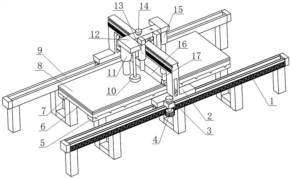
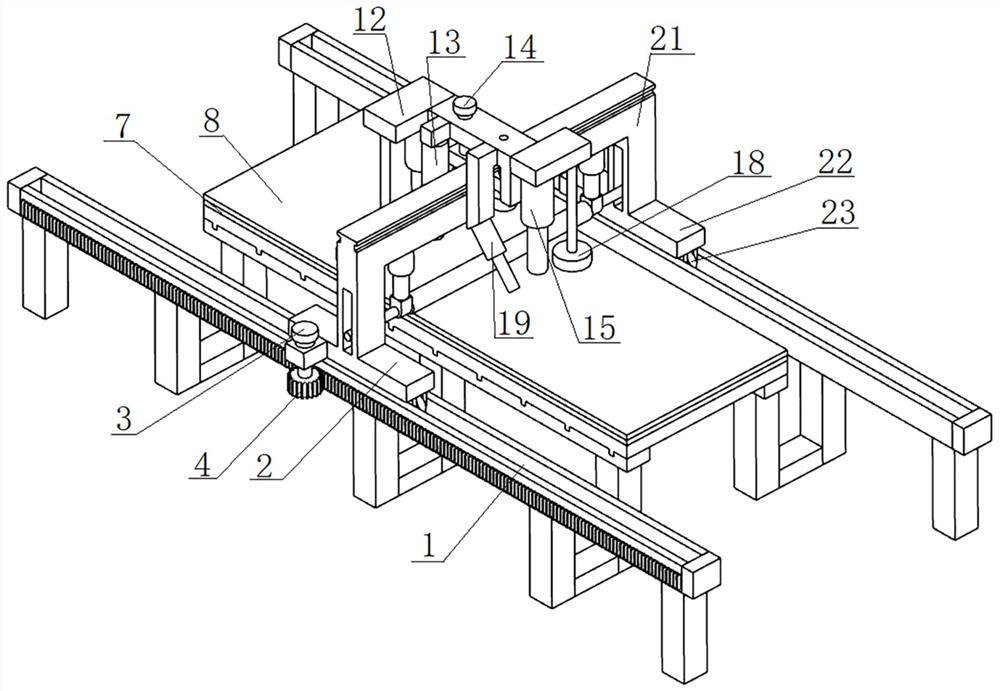
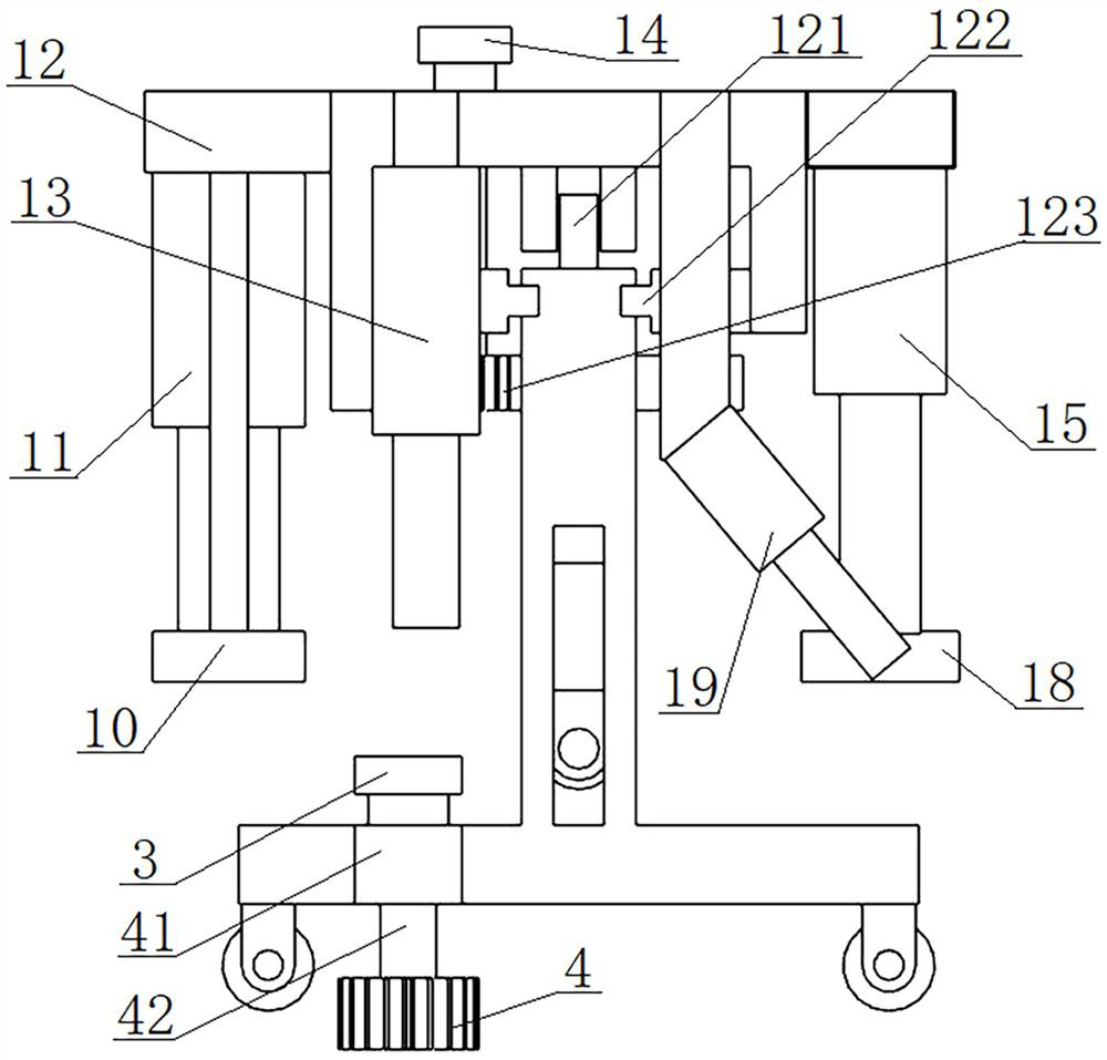
[0039] see figure 1 , figure 2 , image 3 and Figure 6 , a steel back barb equipment, comprising a support frame 5, a first longitudinal rail 1 and a second longitudinal rail 9 respectively arranged on both sides of the support frame 5 and parallel to each other, slidably arranged on the first longitudinal rail 1 and the second longitudinal rail 9 The vertical moving frame 2 on the two vertical rails 9, the horizontal moving frame 12 slidably arranged on the vertical moving frame 2, the horizontal moving frame 12 is integrated with a numerical control cutting machine 11, a vacuum cylinder 13, a glue dispenser 19 and a point welding machine 15;

[0040] A power mechanism 1 is arranged on the longitudinal moving frame 2, and a power mechanism 2 is arranged on the transverse moving frame 12;

[0041] A support plat...


PUM


Abstract

The invention provides steel back barb equipment and method. The steel back barb equipment comprises a supporting frame, a first longitudinal rail, a second longitudinal rail, a longitudinal moving frame and a transverse moving frame, wherein the first longitudinal rail and the second longitudinal rail are arranged on the two sides of the supporting frame respectively and are parallel to each other; the longitudinal moving frame is arranged on the first longitudinal rail and the second longitudinal rail in a sliding mode; a numerical control cutting machine, a vacuum cylinder, a dispensing machine and a spot welding machine are integrally arranged on the transverse moving frame; a first power mechanism is arranged on the longitudinal moving frame, and a second power mechanism is arranged on the transverse moving frame. A supporting plate is arranged on the supporting frame, and a first steel layer plate and a second steel layer plate are sequentially arranged on the supporting plate from bottom to top. According to the steel backing barbing equipment and method, barbing can be efficiently carried out on the steel backing, a new barbing process is provided, the working efficiency is greatly improved, barbing is uniform, and the technical effects of semi-automation and even automation are achieved.

Description

technical field [0001] The invention belongs to the technical field of steel back processing, and in particular relates to a steel back barb equipment and method. Background technique [0002] At present, in order to make the friction material and the steel back of the brake pad firmly attached together, it is often adopted to process a certain density of protrusions or pits on the steel back of the brake pad, that is, to set a barb mechanism on the contact surface of the steel back. . For example, the Chinese invention patent with application number CN202010665042.2 discloses a stabbing device for high-strength motorcycle steel back based on the contact surface barb mechanism, and the steel back is stabbed at one time by the barb machine; the application number is CN201620456414. The Chinese utility model patent of X discloses an automatic steel back barb machine, which uses a barb tool to stab the steel back; the Chinese utility model patent with the application number CN...

Claims


Application Information

Patent Timeline
Patent Type & Authority Applications(China)
IPC IPC(8): B23P23/04B23P15/00
CPCY02P70/10F16D69/04B23P15/18F16D2069/0491B23C3/30B23K11/11B23Q15/12B25B11/005F16D2250/003
Inventor 冯兴平毕德忠冯东平
Owner 烟台兴创汽车配件有限公司
Why Eureka
Try Eureka