Rolling sagger and powder sintering method

A technology for saggar and powder materials, which is applied in the field of rolling saggar and powder sintering. It can solve the problems of difficult sintering, damage to saggar ceramic materials, and restrictions on the structure of rolling saggar. It achieves a simple and reliable fixed structure and reduces processing costs. Difficulty, the effect of reducing expansion stress

Pending Publication Date: 2022-04-15
JIANGSU JITRI MOLECULAR ENG INST CO LTD
View PDF1 Cites 0 Cited by
  • Summary
  • Abstract
  • Description
  • Claims
  • Application Information

AI Technical Summary

Problems solved by technology

Inventor also does not provide corresponding solution in aforementioned patent document
[0005] In addition, in order to meet the chemical stability and mechanical strength at high temperature, the existing saggar liners are usually made of ceramic materials, but the sintering of large-volume ceramic sagger liners is too difficult, the cost is extremely high, and thermal expansion and contraction are also easy to cause Damage to the ceramic material of the sagger
In addition, although there are many options for connecting the cover plate to the main body at room temperature (such as threads, bolts, buckles, etc.), the above-mentioned structure is prone to deformation, adhesion and other problems at high temperatures, making it difficult to install the cover plate after cooling down. The cover is separated from the sagger body
These issues further limit the implementation of rolling saggar structures

Method used


Image

  • Rolling sagger and powder sintering method
  • Rolling sagger and powder sintering method
  • Rolling sagger and powder sintering method

Examples


Embodiment 1

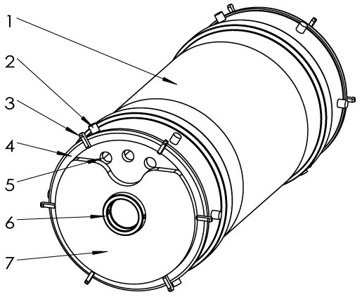
[0027] figure 1 and figure 2Shown is a specific structure of a rolling sagger of the present invention, including a sagger main body 1, which is a hollow cylinder surrounding the inner cavity and has a horizontal axis of rotation. A number of fixed columns 2 are fixed, and the two ends of the sagger main body 1 are detachably connected with a fixed cover 4. The fixed cover 4 is a circular plate, and its outer periphery is fixed with a number of fixed hooks 3. The number of fixed hooks 3 And the position is in one-to-one correspondence with the fixed column 2. The fixed cover plate 4 is provided with a through vent hole 5 , and the vent hole 5 communicates with the inner cavity of the sagger main body 1 . A side of the fixed cover 4 away from the sagger body 1 (hereinafter referred to as “outer side”) is fixed with a fixed shaft 6 , and the fixed shaft 6 is located at the geometric center of the fixed cover 4 . The outer side of the fixed cover plate 4 is provided with a mo...

Embodiment 2

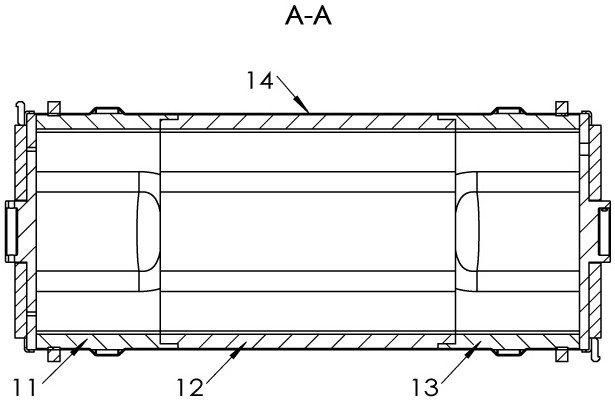
[0031] A powder sintering method using the above-mentioned rolling sagger, comprising the following steps: putting powdery materials into the sagger main body 1, covering the opening end of the sagger main body 1 with the fixed cover plate 4, and making the fixed hook 3 and the fixed hook 3 The positions of the columns 2 correspond one by one, and each set of corresponding fixed hooks 3 and the fixed columns 2 are respectively connected and fixed together with detachable connectors. In this embodiment, the connectors are metal wires, and the powdery The rolling sagger of the material is put into the pusher tunnel kiln for high-temperature sintering, the rolling sagger rolls forward in the pusher tunnel kiln, and the movable cover 7 keeps the center of gravity lower than the fixed shaft 6 during the tumbling under the action of gravity and makes the At least one exhaust hole 5 on the upper part of the fixed cover plate 4 is in a connected state, and the rest of the exhaust holes...


PUM


Abstract

The invention discloses a rolling sagger and a powder sintering method, and relates to the technical field of high-temperature sintering kilns. The rolling sagger comprises a sagger main body, the sagger main body is a hollow cylinder forming an inner cavity in a surrounding mode and is provided with at least one rotation axis, the two ends of the sagger main body are detachably connected with fixed cover plates, the fixed cover plates are provided with through exhaust holes, and the exhaust holes are communicated with the inner cavity of the sagger main body; a fixed shaft and a movable cover plate are arranged on the outer side of the fixed cover, the movable cover plate is in close fit with the outer side of the fixed cover plate and enables part of the exhaust holes to be in a blocked state, a notch is formed in the movable cover plate, the notch corresponds to at least one exhaust hole and enables the exhaust hole to be in a communicated state, and the movable cover plate can rotate around the fixed shaft. According to the rolling sagger and the powder sintering method, when the rolling sagger rolls in the tunnel kiln, waste gas can be discharged while powder is reserved.

Description

technical field [0001] The invention belongs to the technical field of high-temperature sintering kilns, and in particular relates to a rolling sagger and a powder sintering method. Background technique [0002] High-temperature sintering furnace is an important heating equipment commonly used in industry, and is widely used in powder sintering or green body sintering of active metals, refractory metals and their alloys, ceramic materials, and dissimilar materials. Traditional high-temperature sintering furnaces can be mainly divided into pusher kilns and rotary furnaces according to their structures. The main body of the pusher kiln is a tunnel-type high-temperature kiln body. The saggers containing the materials to be sintered are lined up and pushed forward from the kiln head to the kiln body. After several hours of high-temperature sintering in the kiln, the saggers are constantly being fired. The horizontal sequence moves, but the position of each sagger remains unchan...

Claims


Application Information

Patent Timeline
Patent Type & Authority Applications(China)
IPC IPC(8): F27D5/00B22F3/10
Inventor 霍继延陈建中
Owner JIANGSU JITRI MOLECULAR ENG INST CO LTD
Why Eureka
Try Eureka