
Gear fault classification detection method and system based on meshing rigidity identification

A technology of fault classification and meshing stiffness, applied in the field of machining, can solve the problems of high false alarm rate, identification, and inability to achieve meshing stiffness, and achieve the effect of clear physical meaning

Active Publication Date: 2022-04-15
SHANGHAI JIAO TONG UNIV
View PDF12 Cites 3 Cited by
  • Summary
  • Abstract
  • Description
  • Claims
  • Application Information

AI Technical Summary

Problems solved by technology

[0005] In view of the existing technology, the present invention does not have the ability to analyze and describe the whole process of gear meshing to box vibration, and cannot realize the identification of meshing stiffness, so that the weakening of signal characteristics caused by the coupling effect of the structural transmission path cannot be eliminated in the obtained vibration signal Even the defect of changing, and the inability of the existing technology to achieve both classification and diagnosis of faults and physical explainability, and it is easily disturbed by changes in working conditions such as the position of the measuring point, speed, load, etc., resulting in a high rate of false alarms, A gear fault classification detection method and system based on the identification of meshing stiffness is proposed, combined with dynamics and transfer path modeling methods, an analytical mathematical description of the vibration transfer from gear meshing to box vibration is established, and the structural transfer in the identified meshing stiffness The effect of the path is eliminated, so it can be used for fault classification detection

Method used


Image

  • Gear fault classification detection method and system based on meshing rigidity identification
  • Gear fault classification detection method and system based on meshing rigidity identification
  • Gear fault classification detection method and system based on meshing rigidity identification

Examples


Embodiment Construction

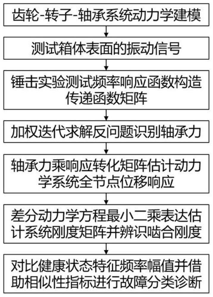
[0035] Such as figure 1 As shown, this embodiment relates to a gear fault classification and detection method based on box vibration identification of meshing stiffness, including:

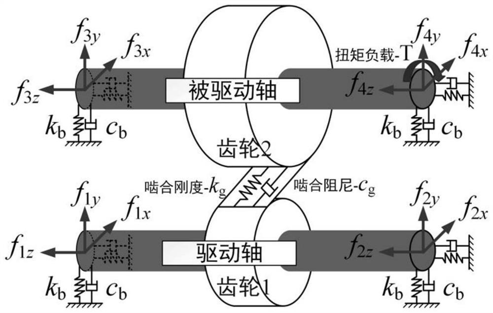
[0036] Step 1: System dynamics modeling: Obtain relevant mechanical parameters according to the gear, shaft and bearing drawings in the gearbox, according to figure 2 The dynamic modeling of the gear-rotor-bearing system shown schematically constructs a dynamic differential equation model, specifically: Among them: M, D, K represent the mass matrix, damping matrix and stiffness matrix respectively, F represents the load, u is the displacement vector; the stiffness matrix k includes the bearing stiffness k b and the meshing stiffness of the gear to be identified, the damping matrix includes the bearing damping c b ; f is the bearing force, which is obtained by the product of bearing stiffness and bearing node displacement, that is, f=k b u, all the bearing forces together constitute the bearin...


PUM


Abstract

The invention discloses a gear fault classification detection method and system based on meshing rigidity. A dynamic differential equation model is constructed for a gear box, and a box body vibration signal vector matrix generated by the gear box to be detected in a stable operation state under the given rotating speed and load is collected; carrying out corresponding bearing force modeling according to the type of a meshing gear, and reconstructing a box vibration signal vector matrix to obtain a bearing force intermediate variable and a displacement vector of a full node; and finally, gear meshing rigidity is obtained through the full-node displacement vector, and gear fault classification is realized by extracting the amplitude at the characteristic frequency. According to the method, dynamics and a transmission path modeling method are combined, an analytic mathematical description of vibration transmission in the whole process from gear meshing to box vibration is established, the influence of a structure transmission path in the identified meshing rigidity is eliminated, and therefore the method can be used for fault classification detection.

Description

technical field [0001] The invention relates to a technology in the field of mechanical processing, in particular to a gear fault classification and detection method based on box vibration identification of meshing stiffness. Background technique [0002] As a key mechanical component of gear transmission systems, gearboxes play a vital role in industries such as aerospace, automotive, and wind turbines. To avoid unnecessary downtime, costly repair procedures and even casualties, vibration sensing-based gearbox fault diagnosis and condition monitoring have long been of interest. The mainstream method is to extract the fault characteristics from the time domain or frequency domain of the vibration signal, and then judge whether a fault occurs according to the change of the characteristics and the fault mechanism. In order to ensure that the extracted fault features are more sensitive to faults, signal decomposition methods (such as nonlinear frequency modulation component de...

Claims


Application Information

Patent Timeline
Patent Type & Authority Applications(China)
IPC IPC(8): G01M13/028
Inventor 何清波于小洛彭志科
Owner SHANGHAI JIAO TONG UNIV
Learn More