Automobile oil pipe joint machining device and machining method thereof

A technology for oil pipe joints and processing devices, applied in positioning devices, metal processing equipment, metal processing machinery parts, etc., can solve the problems of unstable clamping, vibration noise, low transmission efficiency, low failure rate, etc., and achieve fast and stable conversion. The effect of improving transmission efficiency and low failure rate

Active Publication Date: 2022-04-19
安徽祥源汽车配件制造有限公司
View PDF3 Cites 3 Cited by
  • Summary
  • Abstract
  • Description
  • Claims
  • Application Information

AI Technical Summary

Problems solved by technology

[0005] The invention clamps the workpiece through the splint, so that when the splint clamps the workpiece, it can have a clamping effect on the middle part to the tail of the workpiece, the clamping contact surface is wide, and the workpiece is prevented from shaking left and right with the clamping point as the fulcrum , to ensure the stability of the workpiece during processing, which is conducive to the improvement of processing accuracy, and by driving the cylinder to control the movement of the main drive shaft, a set of motors can not only drive the splint to lock, but also drive the drum to rotate, reducing the number of motors The number is beneficial to reduce the cost of equipment and ensure that the equipment has a lower failure rate. In addition, the motor in the present invention adopts a fixed installation structure, which ensures the stability of the motor itself, effectively reduces vibration and noise, and improves transmission efficiency. When the transmission gear switches the meshing state, through the sliding of the transmission gear on the main drive shaft and the compression of the return spring, the rapid adjustment when the transmission gear overlaps with the locking gear or the drive gear can be realized, ensuring the smooth connection of the transmission gear, making The transition between the gear connection states is fast and stable, and it is easy to adjust. It solves the problems of unstable clamping when the auto oil pipe joint is automatically clamped, excessive vibration noise during the use of the motor, and low transmission efficiency. A processing device for automobile oil pipe joints is proposed. and its processing method

Method used


Image

  • Automobile oil pipe joint machining device and machining method thereof
  • Automobile oil pipe joint machining device and machining method thereof
  • Automobile oil pipe joint machining device and machining method thereof

Examples


Embodiment 1

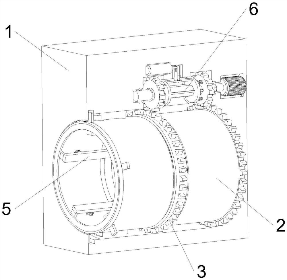
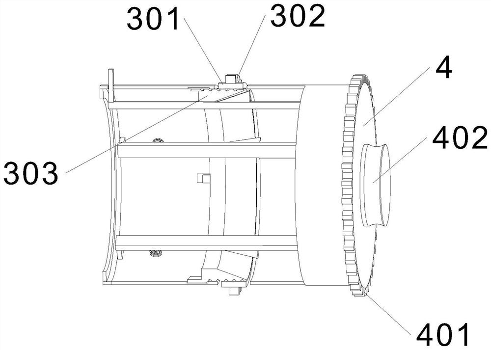
[0038] see Figure 1-Figure 5 As shown, the outer frame 1 is an integral part of the equipment, and other equipment is externally connected to the outside, and the rotating cylinder 2, the driving mechanism 6, the driving cylinder 13, the connecting rod 12 and the push plate 11 connected to the driving cylinder 13 are connected in rotation. , the drum 2 is divided into two parts by the locking mechanism 3, wherein the front part of the drum 2 is provided with an opening, which can be put into the workpiece to be processed, and the rear part of the drum 2 is fixedly installed with a drive plate 4, and the outside of the drive plate 4 is fixedly connected with a bearing Bearing 402, the rotation of the drum 2 in the outer frame 1 is supported by bearings, the outer wall of the front part of the drum 2 and the outer wall of the bearing bearing 402 are all provided with bearings, and the rotation of the drum 2 in the bearing reduces the time when the drum 2 rotates. The resistance...

Embodiment 2

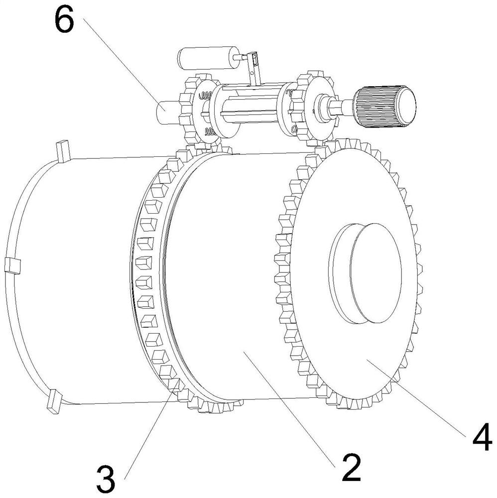
[0040] see Figure 6-Figure 7 As shown, the driving mechanism 6 is also arranged inside the outer frame 1, and the driving mechanism 6 is located above the drum 2. The driving mechanism 6 includes a main driving shaft 601, a hexagonal output shaft 602, a servo motor 603 and a side locking plate 604. The main driving shaft One end of 601 is slidably connected inside the outer frame 1, and the main drive shaft 601 can rotate and translate in the axial direction inside the outer frame 1. The other end of the main drive shaft 601 is provided with a hexagonal interface, and the main drive shaft 601 slides through this structure Connected to the outer wall of the hexagonal output shaft 602, through this structure, the hexagonal output shaft 602 can drive the main drive shaft 601 to rotate without slipping, and at the same time, the main drive shaft 601 can slide freely in the axial direction on the hexagonal output shaft 602, ensuring The freedom of movement of the main drive shaft ...

Embodiment 3

[0042] see Figure 6-Figure 8 As shown, the outer wall of the main drive shaft 601 is also fixedly connected with two sets of support plates 8, the two sets of support plates 8 are located between the two sets of transmission gears 7, the support plates 8 are fixedly connected with the main drive shaft 601, so that the support plates 8 can Drive main drive shaft 601 to move, be provided with push plate 11 between two groups of support plates 8, the length of push plate 11 is less than the distance between two groups of support plates 8, make push plate 11 and support plate 8 when not working Keep slack to reduce the wear and tear of the contact between the support plate 8 and the push plate 11. The middle part of the push plate 11 is rotatably connected with a connecting rod 12, and the middle part of the connecting rod 12 is connected to the inside of the outer frame 1 through a rotating shaft, so that the connecting rod 12 can rotate around the middle rotating shaft. The upp...


PUM


Abstract

The invention relates to an automobile oil pipe joint machining technology, in particular to an automobile oil pipe joint machining device and a machining method thereof, and aims to solve the problems that clamping is unstable during automatic clamping of an automobile oil pipe joint, vibration noise is too large in the using process of a motor, and transmission efficiency is low. A workpiece is clamped through the clamping plates, the clamping contact area is wide, the workpiece is prevented from shaking left and right with a clamping point as a fulcrum, the stability of the workpiece in the machining process is guaranteed, the machining precision is improved, the motor is of a fixedly-installed structure, the stability of the motor is guaranteed, vibration and noise are effectively reduced, and the machining precision is improved. The transmission efficiency is improved, when the transmission gear switches the meshing state, through sliding of the transmission gear on the main driving shaft and compression of the reset spring, rapid adjustment can be achieved when the transmission gear is overlapped with the locking gear or the driving gear, smooth connection of the transmission gear is guaranteed, and switching between gear connection states is rapid and stable.

Description

technical field [0001] The invention relates to a processing technology for an automobile oil pipe joint, in particular to an automobile oil pipe joint processing device and a processing method thereof. Background technique [0002] As we all know, oil pipe joints are widely used in the field of engineering technology, such as: fuel and oil pipelines of power machinery, and hydraulic oil pipelines of hydraulic machinery, etc. The machining and production of oil pipe joints need to use clamping devices, although the existing oil pipes The joint processing and clamping device can realize the clamping and processing of the oil pipe joint, but the existing oil pipe joint processing and clamping device is usually a three-jaw chuck. When using it, manual clamping is required, and it cannot be clamped or disassembled by itself. Problems affecting work efficiency; [0003] For example, the patent with the application number CN2021202926946 is specifically a clamping device for proc...

Claims


Application Information

Patent Timeline
Patent Type & Authority Applications(China)
IPC IPC(8): B23Q3/08B23Q3/06
CPCB23Q3/08B23Q3/064
Inventor 苟忠强尹俊舒王曼曼欧阳练君
Owner 安徽祥源汽车配件制造有限公司
Why Eureka
Try Eureka