Crankshaft main journal polishing device

A technology of polishing device and main journal, applied in grinding/polishing safety device, grinding driving device, grinding/polishing equipment, etc., can solve the problems of limited polishing work efficiency, poor polishing efficiency, difficult to guarantee accuracy, etc. Improve polishing effect, good applicability, effect of changing height

Active Publication Date: 2022-04-19
罡阳轴研科技(灌云)有限公司
View PDF10 Cites 0 Cited by
  • Summary
  • Abstract
  • Description
  • Claims
  • Application Information

AI Technical Summary

Problems solved by technology

The existing treatment method is to directly use sandpaper to manually polish the journal. The polishing quality depends entirely on the operator’s experience during the polishing operation. This polishing method is time-consuming, laborious, poor in polishing efficiency, and difficult to guarantee accuracy.
[0004] Although the equipment for polishing crankshafts has appeared on the market, since crankshafts are used in different machines, their sizes and styles are also relatively diverse, and different machines The parameters of the main journal of the crankshaft are also different, and the existing polishing device cannot be adjusted freely according to the size of the crankshaft, which greatly limits the efficiency of the polishing work

Method used


Image

  • Crankshaft main journal polishing device
  • Crankshaft main journal polishing device
  • Crankshaft main journal polishing device

Examples


Embodiment 1

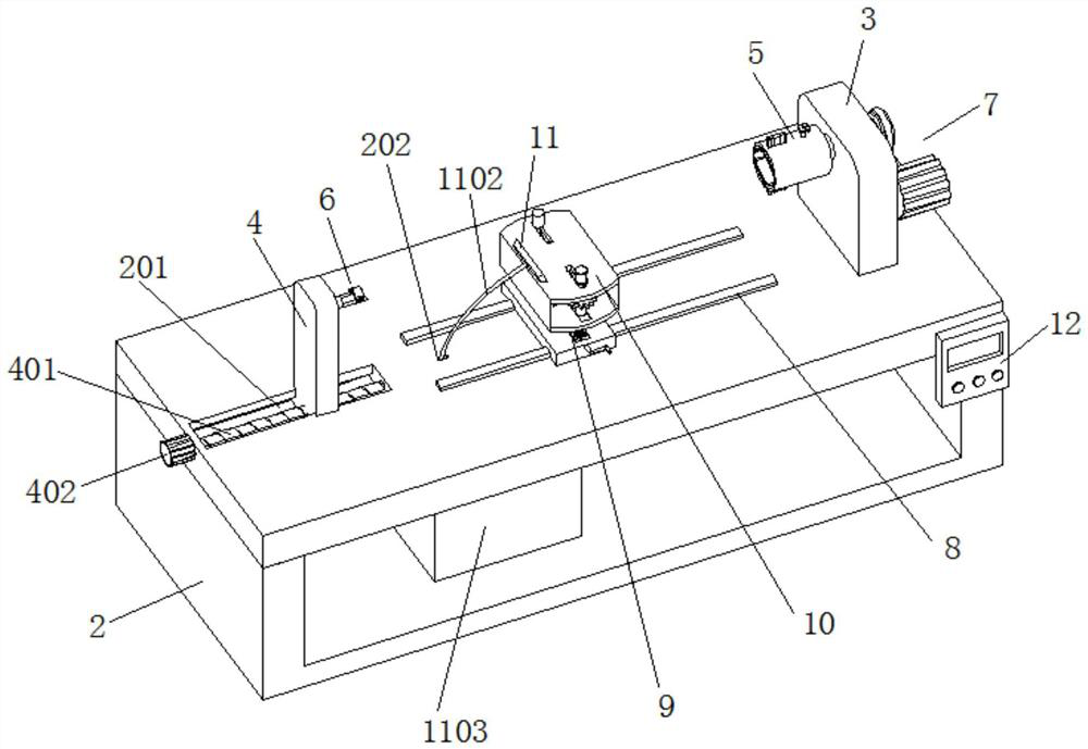
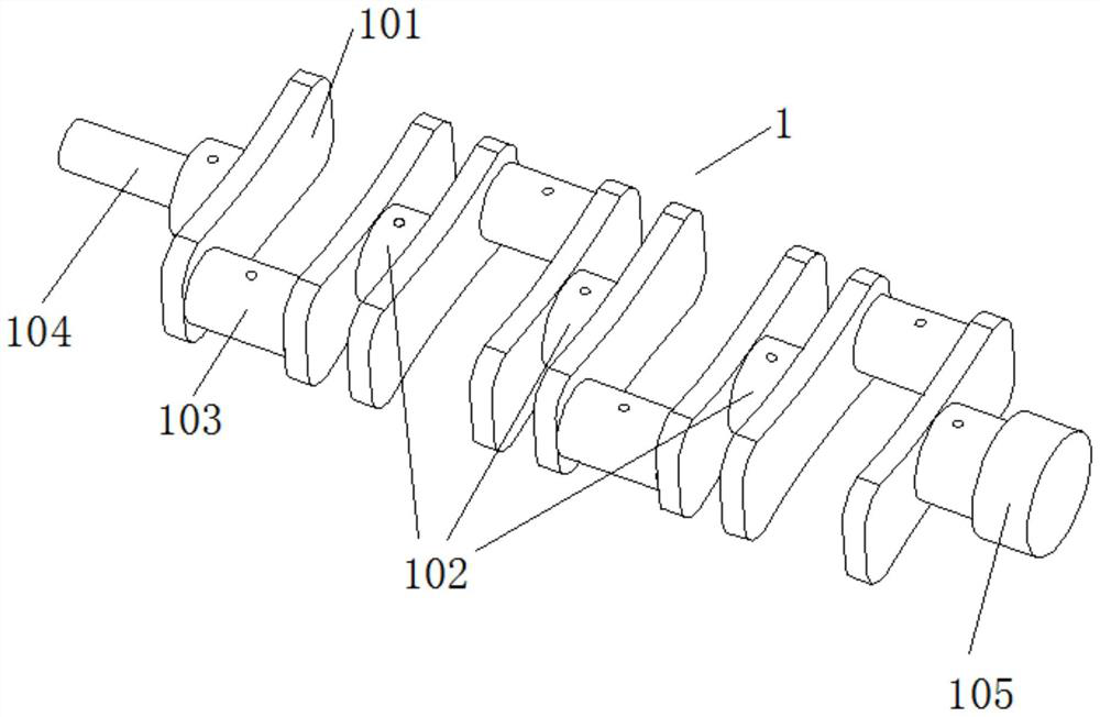
[0056] Embodiment 1 discloses a crankshaft main journal polishing device, refer to the attached figure 1 to attach image 3 , including a processing table 2 for placing the crankshaft 1. The crankshaft 1 is composed of a balance weight 101, a main journal 102, and a connecting rod journal 103 arranged in sequence. The flange end locator 5 and the shaft end locator 6 are installed on the left and right ends through the vertical plate 3 and the distance adjustment plate 4 respectively, and a polishing assembly is installed between the vertical plate 3 and the distance adjustment plate 4 through the electric slide rail 8 10. The bottom of the polishing component 10 is equipped with a lifting component 9, and a control panel 12 as a control center is installed on one side of the processing table 2;

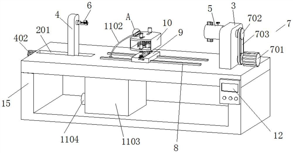
[0057] Reference attached figure 2 And attached Figure 4 , the vertical plate 3 is fixedly installed on one end of the processing table 2 and the flange end locator 5 is movably ...

Embodiment 2

[0067] Reference attached figure 1 And attached Figure 10 At one side of the top of the polishing assembly 10, an adsorption assembly 11 is also provided. The adsorption assembly 11 includes a dust suction cover 1101 arranged on one side of the oilstone grinding wheel 1010 and the sandpaper grinding wheel 1011. The other end of the pipe 1102 passes downwards through the surface of the processing table 2 and is connected to a dust collection box 1103. A suction fan 1104 is arranged on one side of the dust collection box 1103, and an electromagnetic block 1105 is symmetrically arranged on the inner wall of the dust collection cover 1101.

[0068] The principle of the crankshaft main journal polishing device disclosed in embodiment 2 is as follows:

[0069] The debris produced by grinding is absorbed by the dust collection cover 1101, and then enters the dust collection box 1103 through the suction pipe 1102, and the electromagnetic block 1105 in the dust collection cover 1101 ...


PUM


Abstract

The invention discloses a crankshaft main journal polishing device, and relates to the technical field of crankshaft machining, the crankshaft main journal polishing device comprises a machining table, the left end and the right end of the top of the machining table are provided with a flange end positioner and a shaft head end positioner through a vertical plate and a distance adjusting plate respectively, and a polishing assembly is further installed between the vertical plate and the distance adjusting plate through an electric sliding rail; a lifting assembly is arranged at the bottom of the polishing assembly, and an adsorption assembly is further arranged on one side of the top of the polishing assembly. The crankshaft main journal polishing device can be suitable for polishing crankshaft main journals of different models, adjustment is convenient, and the polishing effect can be effectively improved under dual polishing of oilstones and abrasive paper.

Description

technical field [0001] The invention relates to the technical field of crankshaft processing, in particular to a crankshaft main journal polishing device. Background technique [0002] The crankshaft is the main rotating part of the engine. After the connecting rod is installed, the up and down reciprocating motion of the connecting rod can be converted into a rotating motion. The crankshaft is mostly made of carbon structural steel or ductile iron, and has two important parts: the main journal and the connecting rod journal. The main journal is installed on the cylinder block, the connecting rod journal is connected with the large end hole of the connecting rod, and the small end hole of the connecting rod is connected with the cylinder piston, forming a typical slider crank mechanism. [0003] In order to reduce the wear of the main journal during work and ensure the smooth operation of the crankshaft, the main journal needs to be polished when processing the crankshaft. ...

Claims


Application Information

Patent Timeline
Patent Type & Authority Applications(China)
IPC IPC(8): B24B29/04B24B27/02B24B5/42B24B41/06B24B55/00B24B55/06B24B47/12B24B47/04
CPCB24B29/04B24B27/02B24B5/42B24B5/421B24B41/067B24B55/00B24B55/06B24B47/12B24B47/04
Inventor 金步旺陈善兵许学勇孙小雨
Owner 罡阳轴研科技(灌云)有限公司
Why Eureka
Try Eureka