
Two-dimensional large-view-field imaging plane symmetric free-form surface optical system

An imaging plane and optical system technology, applied in the optical field, can solve the problems of weak aberration correction ability, low imaging quality, difficult to reduce weight, etc., and achieve the effect of small distortion, good imaging quality and compact structure

Active Publication Date: 2022-04-19
CHANGCHUN INST OF OPTICS FINE MECHANICS & PHYSICS CHINESE ACAD OF SCI
View PDF6 Cites 1 Cited by
  • Summary
  • Abstract
  • Description
  • Claims
  • Application Information

AI Technical Summary

Problems solved by technology

However, it still cannot meet the needs of more and more applications for the expansion of the imaging field of view in the Y direction.
Moreover, the existing off-axis four-reverse system has the common disadvantages of off-axis systems, that is, it is bulky and difficult to reduce weight.
For the design of optical systems with large aperture and large field of view, the traditional off-axis reflective optical path has the problems of large volume, high distortion, weak aberration correction ability related to the field of view, and low imaging quality

Method used


Image

  • Two-dimensional large-view-field imaging plane symmetric free-form surface optical system
  • Two-dimensional large-view-field imaging plane symmetric free-form surface optical system
  • Two-dimensional large-view-field imaging plane symmetric free-form surface optical system

Examples


Embodiment 1

[0043] System technical indicators are as follows:

[0044] Working band: infrared band 3μm-5μm;

[0045] Entrance pupil diameter: 400mm;

[0046] Focal length: 600mm;

[0047] Field of view: 18°×9°;

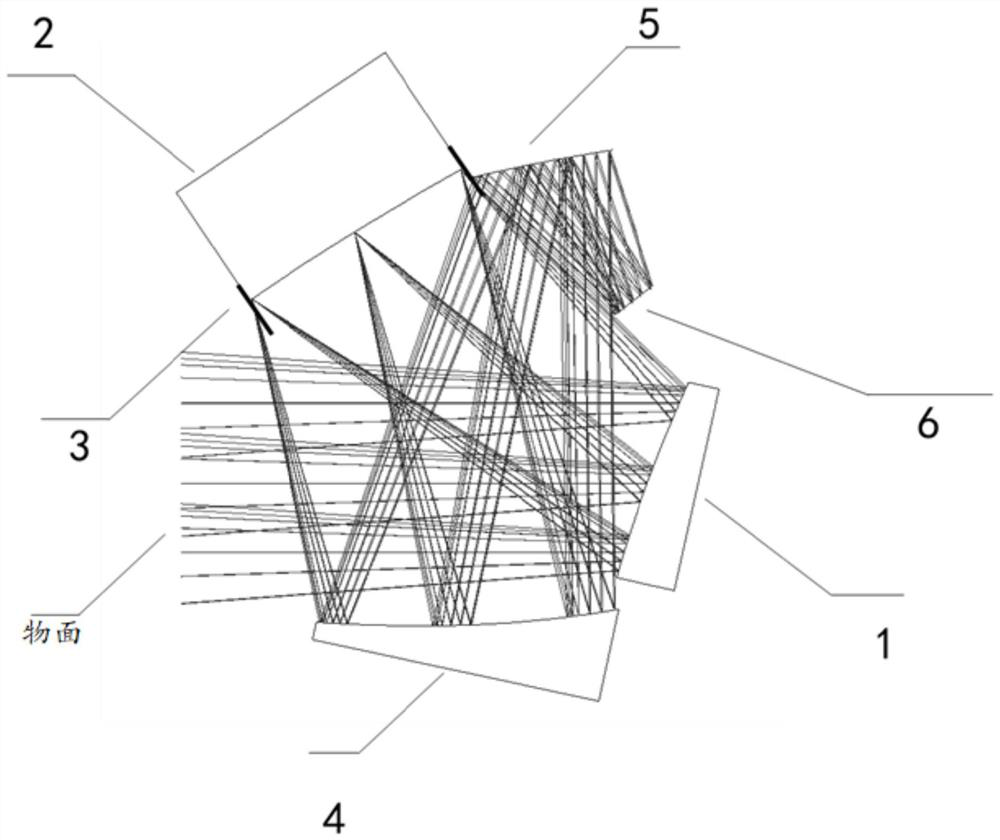
[0048] In the two-dimensional large field of view imaging plane symmetrical free-form surface optical system of this embodiment, the structure of the optical system is as follows figure 1 As shown, in the global coordinates, the vertices of the reflection surface of the first mirror 1, the reflection surface of the second mirror 2, the reflection surface of the third mirror 4, the reflection surface of the fourth mirror 5, and the center of the detector window relative to the object plane See Table 1 below for details of the location data.

[0049] Table 1 The position data of the vertices of each mirror

[0050] surface x y z α β gamma first mirror 0.00000 0 900.00000 -12.5169 0.0000 0.0000 second mirror 0.00000 354.54132 140.85153 -56....


PUM


Abstract

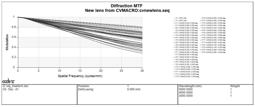
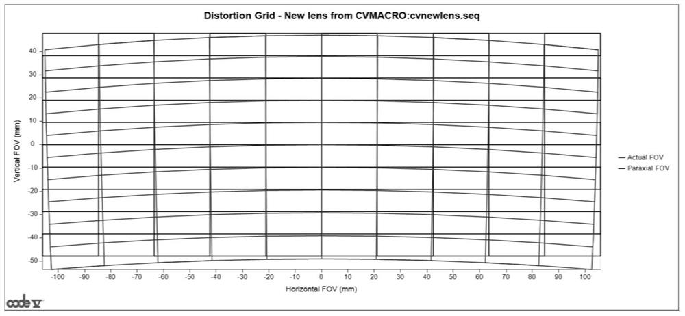
The invention provides a two-dimensional large-field-of-view imaging plane symmetric free-form surface optical system, and relates to the technical field of optics, a first reflector, a second reflector, a third reflector, a fourth reflector and a detector image plane are sequentially arranged in the light path direction, an aperture diaphragm is further arranged, and the position of the aperture diaphragm coincides with the position of the second reflector; the light enters the first reflector, enters the second reflector after being reflected by the first reflector, enters the third reflector after being reflected by the second reflector, enters the fourth reflector after being reflected by the third reflector, and enters the detector image surface for imaging after being reflected by the fourth reflector. The optical system adopts four free-form surface reflectors with symmetrical planes, the four free-form surface reflectors are arranged according to the negative-positive-positive-positive-positive distribution mode of focal power, the inclination angle of the reflectors meets the requirement of anastigmatism, near-diffraction-limit imaging in a 18-degree * 9-degree two-dimensional view field is achieved, distortion correction can be achieved in the infrared band of 3-5 microns through system design, and the resolution ratio of the system is greatly improved. The imaging quality is close to the diffraction limit.

Description

technical field [0001] The invention relates to the field of optical technology, in particular to a two-dimensional large field of view imaging plane symmetrical free-form surface optical system. Background technique [0002] Off-axis reflective optical systems have been used in many fields, especially in the field of cryogenic optics, due to their advantages of no chromatic aberration, good heat resistance, and low thermal noise. However, off-axis reflective optical systems using traditional curved surfaces such as quadric surfaces and even-order aspheric surfaces are difficult to simultaneously achieve the requirements of large aperture, large field of view, and compact envelope due to the small number of available design variables. [0003] At present, the off-axis system with relatively mature technology and the most widely used is the off-axis three-mirror system, but the optimization degree of freedom of the three-reflector system is relatively small, which limits the ...

Claims


Application Information

Patent Timeline
Patent Type & Authority Applications(China)
IPC IPC(8): G02B17/06G02B27/00
CPCG02B17/0663G02B27/0012G02B17/0848
Inventor 王灵杰张新吴洪波赵尚男
Owner CHANGCHUN INST OF OPTICS FINE MECHANICS & PHYSICS CHINESE ACAD OF SCI
Learn More