Intelligent charging pile
An intelligent charging and circuit technology, applied in charging stations, electric vehicle charging technology, electric vehicles, etc., can solve the problems of slow power replenishment and difficulty in finding charging piles, etc., and achieve the effect of prolonging battery life
- Summary
- Abstract
- Description
- Claims
- Application Information
AI Technical Summary
Problems solved by technology
Method used
Image
Examples
Embodiment 1
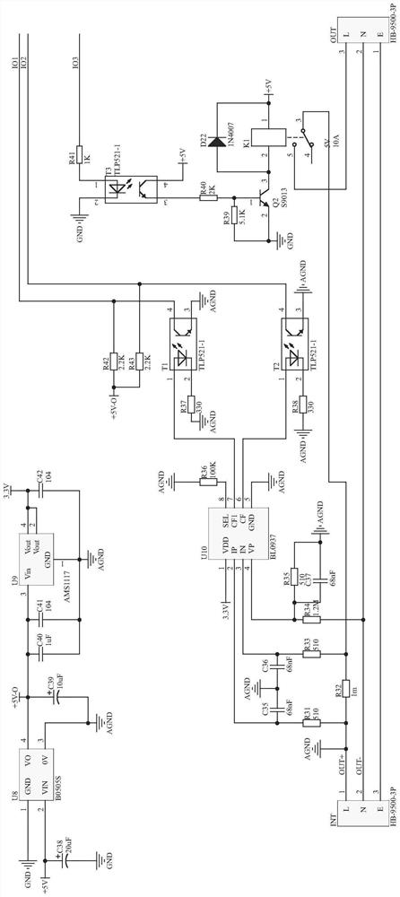
[0032] Example 1, such as Figure 1-9 As shown, an intelligent charging pile is provided, including an intelligent charging pile for charging a battery pack of an electric vehicle, the intelligent charging pile has: an internal energy storage for storing and outputting electric energy; The charging coupling interface between the intelligent charging pile and the electric vehicle; the control circuit for the intelligent charging pile; the control circuit of the intelligent charging pile includes: a main control module, a power supply circuit, a detection circuit, a driving circuit, a debugging circuit, a distance sensing circuit, an inverter Transformation circuit, card swiping circuit, and communication circuit, the power supply circuit performs charging and discharging and detection of the battery, the driving circuit provides power support for the movement of the intelligent charging pile, and the debugging circuit can debug the current and voltage of the circuit. The distan...
Embodiment 2
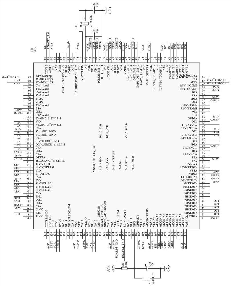
[0033] Example 2, such as figure 1 As shown, the first lead of the pin 160 of the chip U11 is connected to the power supply through the resistor R50, the second lead is grounded through the capacitor C43, the switch S1 is set at both ends of the capacitor C43, the pin 77 of the chip U11 The first lead is connected to the pin 2 of the crystal oscillator X1, the second lead is grounded through the capacitor C45, and the model of the chip U11 is TMS320F2812PGFA_176.
Embodiment 3
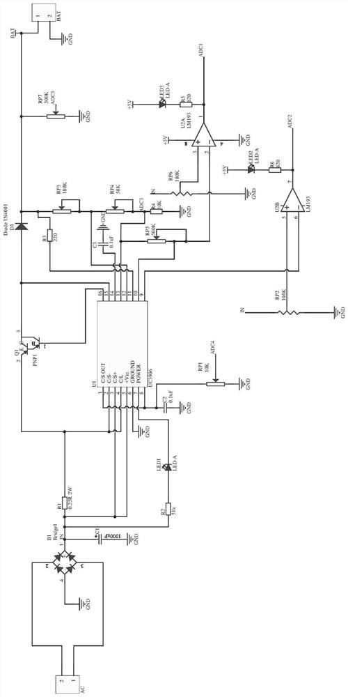
[0034] Example 3, such as figure 2 As shown, the power supply circuit includes a battery charging circuit and a detection circuit. The battery charging circuit includes chips U1, U2A, and U2B. Pin 2 of the chip U1 is grounded through a resistor R1 and a rectifier bridge, and pins 3 and 5 are grounded through a rectifier bridge. Capacitor C1 is grounded, pin 4 is connected to the emitter of triode Q1, pin 7 is grounded through LED1, resistor R2, and the rectifier bridge, pin 8 is grounded through capacitor C2, and pin 16 is connected to the base of the triode Q1 through PNP1. The first lead of the pin 15 is connected to the collector of the triode Q1, the second lead is connected to the positive pole of the power supply BAT through the diode D1, the negative pole of the power supply BAT is grounded, the pin 14 of the chip U1 is grounded through the capacitor C3, and the pin 13 is grounded. The first lead is grounded through resistor R3 and adjustable resistor RP7, the second l...
PUM
 Abstract
Description
Claims
Application Information
 - R&D
- Intellectual Property
- Life Sciences
- Materials
- Tech Scout
- Unparalleled Data Quality
- Higher Quality Content
- 60% Fewer Hallucinations
Browse by: Latest US Patents, China's latest patents, Technical Efficacy Thesaurus, Application Domain, Technology Topic, Popular Technical Reports.
© 2025 PatSnap. All rights reserved.Legal|Privacy policy|Modern Slavery Act Transparency Statement|Sitemap|About US| Contact US: help@patsnap.com


