
Logic gate based on neuromorphic device

A neuromorphic and logic gate technology, applied in the field of logic gates, can solve the problems of poor applicability, low neural network integration, and high power consumption, and achieve the effects of good applicability, reduced power consumption, and good integration.

Pending Publication Date: 2022-04-22
CETHIK GRP
View PDF0 Cites 0 Cited by
  • Summary
  • Abstract
  • Description
  • Claims
  • Application Information

AI Technical Summary

Problems solved by technology

Therefore, in view of the problems that the CMOS logic circuit in the prior art has a low degree of integration with the neural network, poor applicability, and high power consumption, this application proposes a logic gate based on neuromorphic devices.

Method used


Image

  • Logic gate based on neuromorphic device
  • Logic gate based on neuromorphic device
  • Logic gate based on neuromorphic device

Examples


Embodiment 1

[0046] In this embodiment, both the first neuron A and the second neuron B are inhibitory neurons, which suppress the activation of the connected neurons by issuing inhibitory signals when outputting a high level, the third neuron C and the fourth neuron Element D has a fundamental signal of constant 1.

[0047] The NOR gate logic is implemented based on the logic gates of neuromorphic devices, and the following operations are performed:

[0048] When both the first neuron A and the second neuron B output a high level, the third neuron C and the fourth neuron D are inhibited, the membrane potential is lower than the second firing threshold, the output is low, and the fifth neuron Y When the membrane potential is less than the third release threshold, the output is low level;

[0049] When the first neuron A outputs a high level and the second neuron B outputs a low level, the third neuron C is inhibited, the membrane potential is lower than the second firing threshold, the ou...

Embodiment 2

[0063] In this embodiment, both the first neuron A and the second neuron B are inhibitory neurons, which suppress the activation of the connected neurons by issuing inhibitory signals when outputting a high level, the third neuron C and the fourth neuron Element D has a fundamental signal of constant 1.

[0064] The NAND gate logic is implemented based on the logic gate of the neuromorphic device, and the following operations are performed:

[0065] When both the first neuron A and the second neuron B output a high level, the third neuron C and the fourth neuron D are inhibited, the membrane potential is lower than the second firing threshold, the output is low, and the fifth neuron Y When the membrane potential is less than the third release threshold, the output is low level;

[0066] When the first neuron A outputs a high level and the second neuron B outputs a low level, the third neuron C is inhibited, the membrane potential is lower than the second firing threshold, the...


PUM


Abstract

The invention discloses a logic gate based on a neuromorphic device, which comprises a first neuron, a second neuron, a third neuron, a fourth neuron and a fifth neuron, and is characterized in that the first neuron is connected with the third neuron, the second neuron is connected with the fourth neuron, and the third neuron and the fourth neuron are both connected with the fifth neuron; when the membrane potential of the first neuron and the second neuron is greater than or equal to a first issuing threshold value, high level is output, otherwise, low level is output; the third neuron and the fourth neuron have a basic signal, when the membrane potential is the sum of the basic signal and the input signal and is greater than or equal to a second issuing threshold value, a high level is output, otherwise, a low level is output; the fifth neuron and the membrane potential are the sum of the two input signals, when the sum is larger than or equal to a third issuing threshold value, the high level is output, and otherwise, the low level is output. According to the invention, conversion of different logic functions can be realized, low power consumption and non-response performance are realized, and the fusion degree and applicability with a neural network are good.

Description

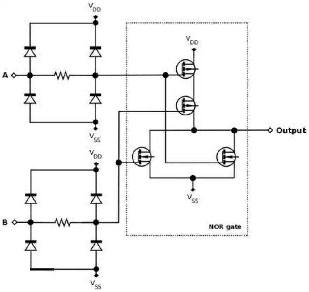
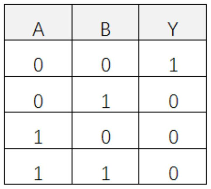
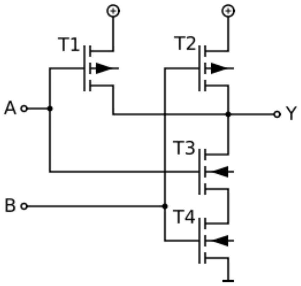
technical field [0001] The invention belongs to the technical field of neuromorphic circuits, and in particular relates to a logic gate based on neuromorphic devices. Background technique [0002] In digital circuits, the so-called "gate" refers to the circuit that can realize the basic logic relationship. Logic gates can be composed of discrete components such as resistors, capacitors, diodes, and triodes, and become discrete component gates. It is also possible to make all the devices and connecting wires of the gate circuit on the same semiconductor substrate to form an integrated logic gate circuit. In the prior art, logic gate circuits are usually realized by CMOS logic, such as figure 1 As shown, the logical expression of the NOR gate is Among them, Y represents the output terminal (Output), A and B are the input terminals respectively, any input terminal is high level (logic 1), and the output is low level (logic 0), figure 2 Shown is the NOR gate truth table. ...

Claims


Application Information

Patent Timeline
IPC IPC(8): G06N3/063H03K19/20
CPCG06N3/063H03K19/20
Inventor 章威林友勇徐庶蔡炎松汤敏贤吴海建吴臻志何伟
Owner CETHIK GRP
Learn More