Organic light-emitting diode production and recovery equipment

A technology of light-emitting diodes and recycling equipment, which is applied to semiconductor devices, electrical components, circuits, etc., can solve the problems of inability to guarantee the overall quality of light-emitting diodes, poor guiding and positioning effects of light-emitting diodes, and inconvenient and stable feeding, so as to reduce collision damage, High practicality, convenient and precise cutting effect

Active Publication Date: 2022-04-22
SHENZHEN ZHUNDU PHOTOELECTRING CO LTD
View PDF1 Cites 0 Cited by
  • Summary
  • Abstract
  • Description
  • Claims
  • Application Information

AI Technical Summary

Problems solved by technology

[0006] The purpose of the present invention is to provide a production and recovery equipment for organic light emitting diodes, so as to solve the problem of poor guiding and positioning effect of light emitting diodes in the above background technology, the overall quality of light emitting diodes cannot be guaranteed after processing, and it is not convenient to Stable feeding and other issues

Method used


Image

  • Organic light-emitting diode production and recovery equipment
  • Organic light-emitting diode production and recovery equipment
  • Organic light-emitting diode production and recovery equipment

Examples


Embodiment 1

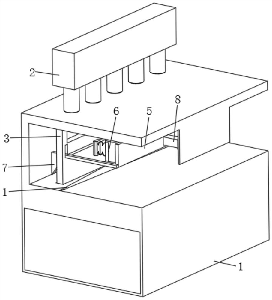
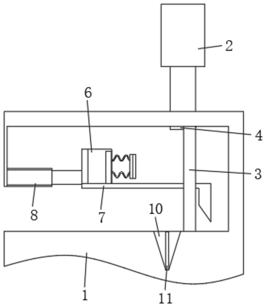
[0033] see Figure 1 to Figure 7 , the embodiment of the present invention provides a kind of organic light-emitting diode production and recycling equipment, which is mainly suitable for the cutting process of light-emitting diodes. The base 301 and the wedge-shaped groove 304 opened on the surface of the base 301, the surface of the base 301 is rotatably installed with several limit assemblies 4 for supporting the light-emitting diodes, the limit assembly 4 includes a receiving tray 403, and the receiving tray 403 in this embodiment The setting is circular, and the surface of the workbench 1 is provided with several round holes corresponding to the material receiving tray 403. The inside of the material receiving tray 403 is slidably installed with a sliding assembly 9, and the surface of the workbench 1 is fixedly installed with a feeding mechanism 2. Because the light-emitting diode is delivered to the corresponding limit component 4 through the round hole with the pin fac...

Embodiment 2

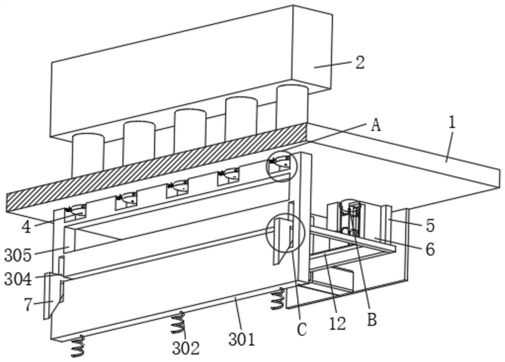
[0039] see Figure 1 to Figure 9 , on the basis of Embodiment 1, a first spring 302 is fixedly installed between the bottom of the base 301 and the surface of the workbench 1, and under the action of the first spring 302, the base 301 always has a tendency to move upward; the base 301 There are several square holes 303 for placing several limiting components 4 through the surface, and an avoidance hole 305 is also formed through the surface of the base 301. The avoidance hole 305 is divided into two parts, and one part corresponds to the cutting mechanism 12 to form an avoidance. The other part is located below the square hole 303, which avoids the processed pins of the light-emitting diodes in the later stage when blanking.

[0040] The receiving tray 403 is divided into two symmetrical and identical semicircles, and each semicircle is provided with a guide hole 404 concave toward the center. Keeping parallel with the base 301, the guide hole 404 is designed in a funnel shap...

Embodiment 3

[0046] see Figure 1 to Figure 10 , on the basis of the second embodiment, the surface of the partition plate 5 and the top of the cutting mechanism 12 are fixedly installed with several mobile assemblies 6 corresponding to the positions of several receiving trays 403 one-to-one, which are used to realize the cutting process. LED protection.

[0047] The moving assembly 6 includes a wedge block 602 and a housing 601 fixedly connected to the partition 5, the wedge block 602 is fixedly connected to the inner wall of the housing 601 through a second spring 603, side plates 604 are slidably installed on both sides of the housing 601, The opposite sides of the two side plates 604 and both sides of the wedge block 602 are provided with corresponding inclined surfaces. When the wedge block 602 is in contact with the two side plates 604 at the same time, pressing the side plates 604 through the inclined surfaces can make the two side plates 604 is relatively far away. In this embodim...


PUM


Abstract

The invention relates to the field of light-emitting diode processing, and discloses organic light-emitting diode production and recovery equipment which comprises a workbench, a lifting assembly is slidably installed in the workbench, and the lifting assembly comprises a base and a wedge-shaped groove formed in the surface of the base. A plurality of limiting assemblies arranged in a rectangular array mode are rotationally installed on the surface of the base, and each limiting assembly comprises a material receiving disc. Through cooperation of the lifting assembly, the limiting assembly, the sliding assembly, the L-shaped connecting rod and the like, automatic guiding and positioning of the light-emitting diode can be achieved, a plug pin cannot be damaged, accurate cutting of the cutting mechanism is facilitated, and the overall quality is guaranteed; after machining is completed, the sliding assembly can play a role in pushing the light-emitting diodes, it is guaranteed that the light-emitting diodes can be rapidly and smoothly separated from the material receiving disc, the speed of the sliding assembly can be automatically reduced so as to reduce instantaneous impact force on the light-emitting diodes, and then damage to the light-emitting diodes is reduced.

Description

technical field [0001] The invention relates to the technical field of light-emitting diode processing, in particular to a production and recovery equipment of organic light-emitting diodes. Background technique [0002] Organic light-emitting diodes (OLEDs) have the same principle of light-emitting as ordinary light-emitting diodes (LEDs), that is, the use of semiconductors to form PN junctions after infiltration of impurities, and electrons are introduced from P-type materials. When electrons meet holes in the semiconductor, it is possible Falling to a lower energy band, a photon with the same energy as the energy gap is emitted, forming a light-emitting diode. [0003] Chinese Patent Publication No. CN112355186A discloses a precision cutting device called a light-emitting diode, including an operating table, a cutting device installed on the top of the workbench, a rotating placement device installed on the top of the workbench, and two placement trays; the present invent...

Claims


Application Information

Patent Timeline
Patent Type & Authority Applications(China)
IPC IPC(8): H01L51/56
CPCH10K71/00
Inventor 祝飞红蓝可发
Owner SHENZHEN ZHUNDU PHOTOELECTRING CO LTD
Why Eureka
Try Eureka