Switching converter and control circuit and control method thereof

A switching converter and control circuit technology, applied in control/regulation systems, DC power input conversion to DC power output, instruments, etc., can solve control system instability, slow transient response of switching converter 100, and output voltage ripple To improve the light load efficiency and stability, take into account the stability and transient performance, and increase the on-time effect

Pending Publication Date: 2022-04-22
SG MICRO
View PDF0 Cites 0 Cited by
  • Summary
  • Abstract
  • Description
  • Claims
  • Application Information

AI Technical Summary

Problems solved by technology

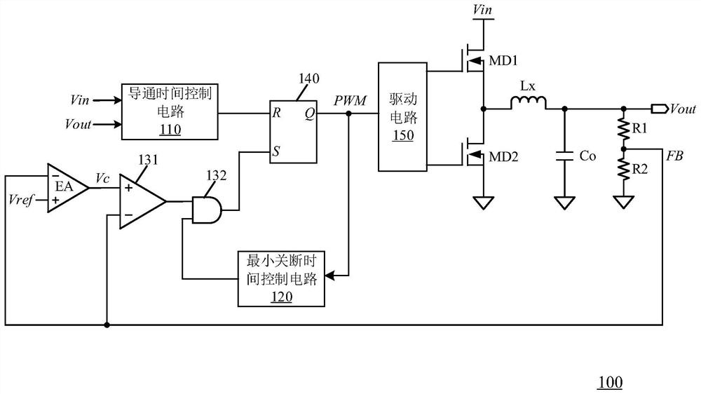
Since this type of output filter produces very little output ripple even in the presence of a lot of noise, and the capacitor ripple is phase delayed compared to the inductor ripple, sub-harmonic oscillations can occur in the system , so it may lead to the instability of the control system
However, using a capacitor with a large ESR (such as an electrolytic capacitor) as the output capacitor at the output end of the switching converter 100 will not only increase the circuit area and cost, but also cause the ripple of the output voltage to increase and cause large fluctuations. normal operation of the stage circuit
[0007] In addition, the transient response of the switching converter 100 in the prior art is relatively slow, and when a large voltage drop event occurs at the load end, the voltage at the output end will change. Limits the application of this control model in areas requiring fast transient response
Moreover, due to the limitation of the conduction time of the switch control signal, the switching converter 100 cannot provide stable power supply when the input voltage Vin and the output voltage Vout are close, which reduces the overall efficiency of the switching converter.

Method used


Image

  • Switching converter and control circuit and control method thereof
  • Switching converter and control circuit and control method thereof
  • Switching converter and control circuit and control method thereof

Examples


Embodiment Construction

[0043] Various embodiments of the invention will be described in more detail below with reference to the accompanying drawings. In the various drawings, the same elements are denoted by the same or similar reference numerals. For the sake of clarity, various parts in the drawings have not been drawn to scale. Also, some well-known parts may not be shown.

[0044] It should be understood that in the following description, a "circuit" refers to a conductive loop formed by at least one element or sub-circuit through electrical or electromagnetic connections. When an element or circuit is said to be "connected to" another element or an element / circuit is said to be "connected between" two nodes, it can be directly coupled or connected to the other element or there can be intervening elements and the connection between elements can be be physical, logical, or a combination thereof. In contrast, when an element is referred to as being "directly coupled to" or "directly connected ...


PUM


Abstract

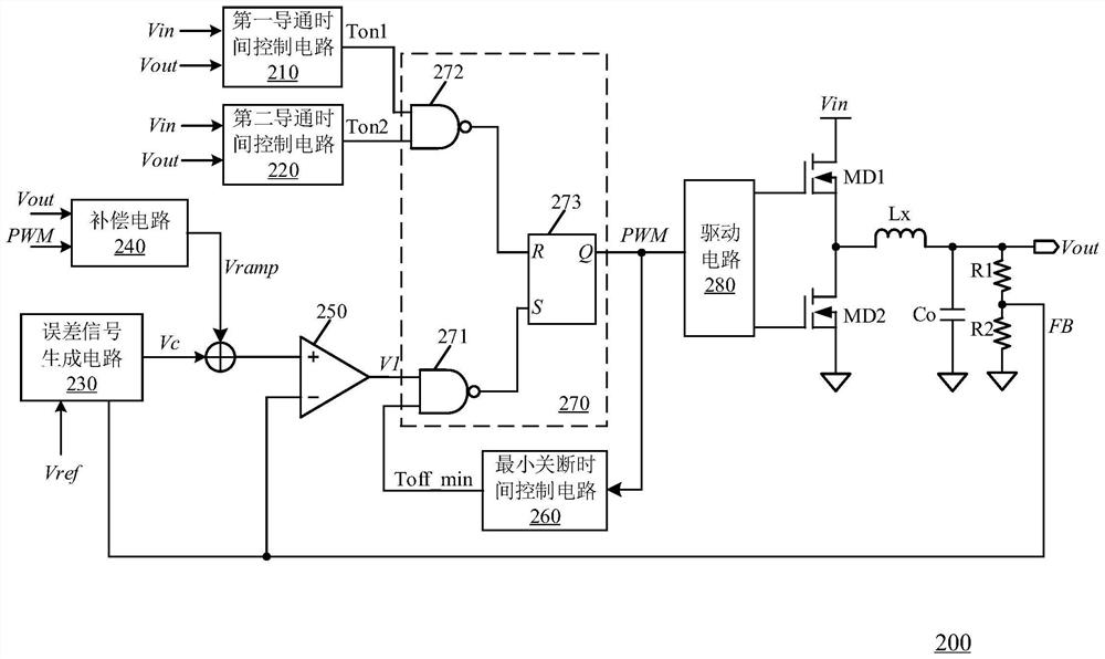
The invention discloses a switching converter and a control circuit and a control method thereof. The control circuit uses a first conduction time control circuit to obtain a first conduction time, and uses a PWM comparator to compare a superposed signal related to an error signal of the DC output voltage with a feedback signal related to the DC output voltage so as to generate an intermediate signal. The switch-on time of the switch tube of the switch converter is adaptively adjusted according to the intermediate signal and the first switch-on time, so that the switch-on time of the switch tube of the switch converter can be prolonged when a voltage drop event occurs at the load end, and the transient performance of the switch converter is improved.

Description

technical field [0001] The present invention relates to the technical field of switching power supplies, and more particularly, to a switching converter and its control circuit and control method. Background technique [0002] Switching converters have been widely used in electronic systems to generate operating voltages and currents required by internal circuit modules or loads. The switching converter uses a power switch tube to control the power transmission from the input terminal to the output terminal, so that a constant output voltage and / or output current can be provided at the output terminal. In switching converters, the ripple-based constant on-time control method has the advantages of good light-load efficiency, fast transient response and easy implementation, so it has been widely used in recent years. [0003] figure 1 A schematic circuit diagram of a switching converter according to the prior art is shown. The switching converter 100 includes a main circuit...

Claims


Application Information

Patent Timeline
Patent Type & Authority Applications(China)
IPC IPC(8): H02M3/158H02M1/088H02M1/14
CPCH02M3/158H02M1/088H02M1/14
Inventor 张宝全孙健李精文
Owner SG MICRO
Why Eureka
Try Eureka